

FANUC A660-8017-T708 Robot Coding Cable: Complete Technical Guide and Applications
On this page
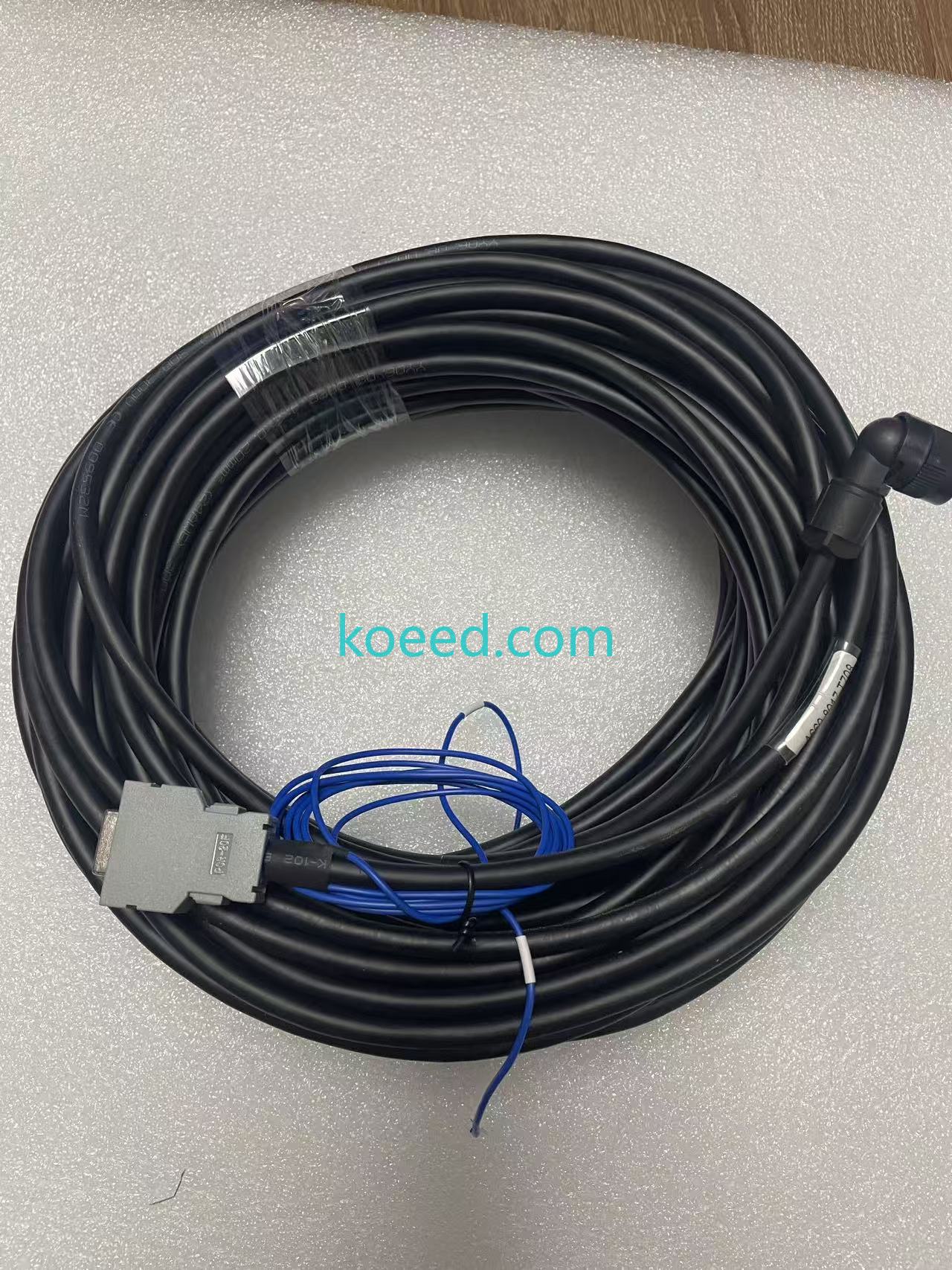
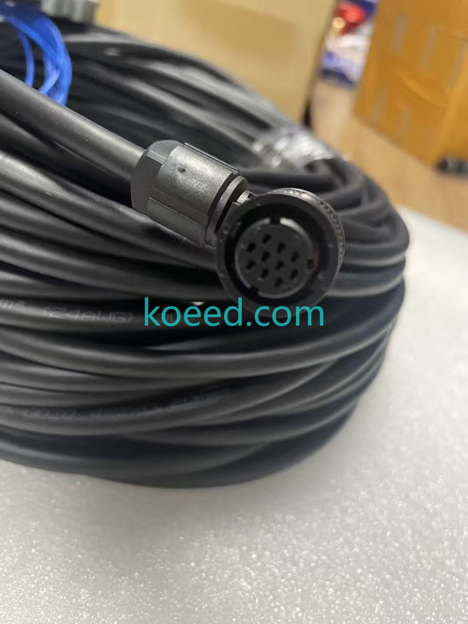
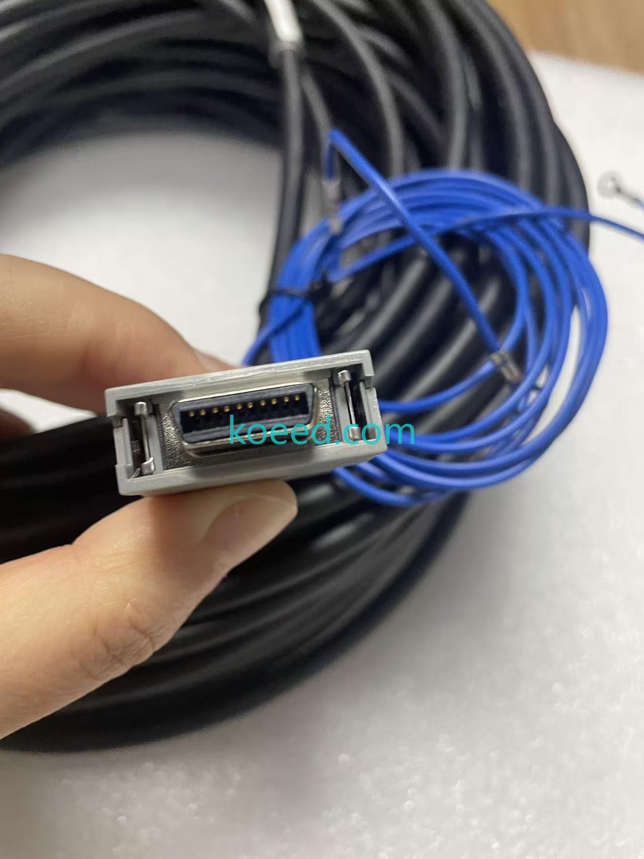
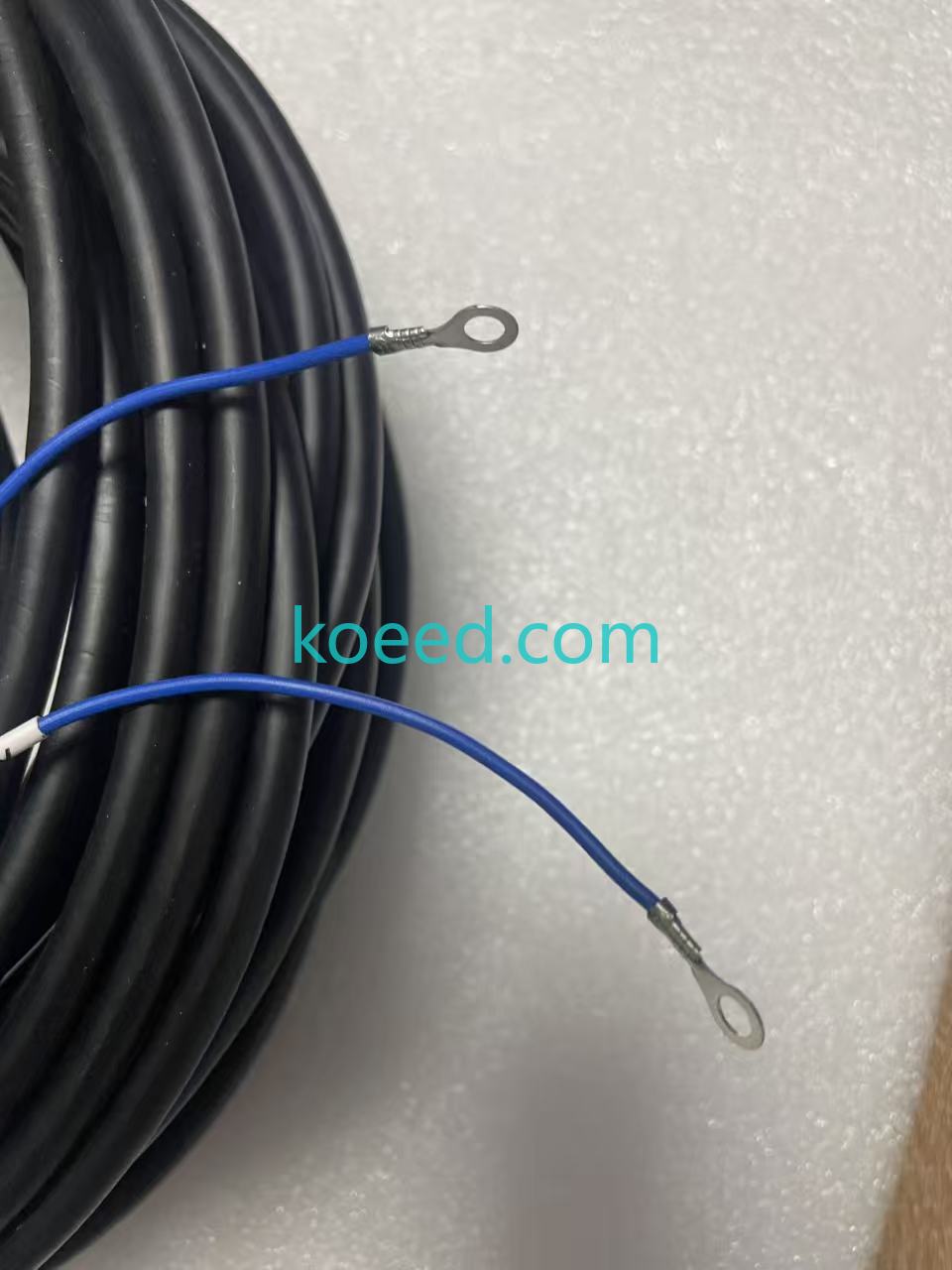
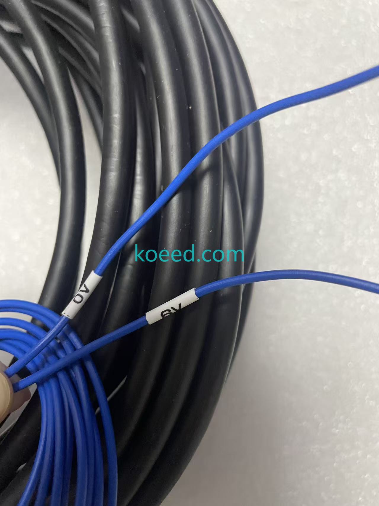
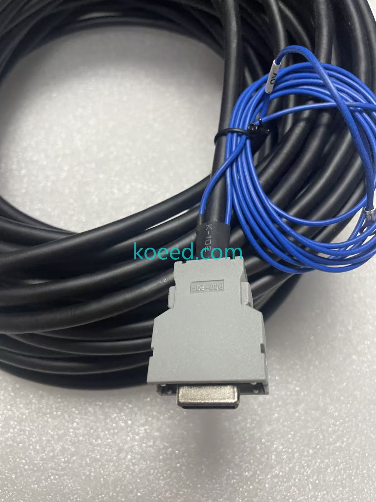
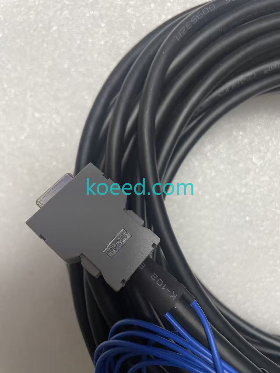
This delivery records one cable assembly under A660-8017-T708, with a recorded length of 30 m. The photographs show a coiled black main cable, a circular socket connector, a rectangular multipin connector and blue auxiliary leads with ring terminals.
Identification and delivery details
The rectangular connector has a metal hood and two retaining screws. The circular connector is shown from the contact face, so its socket layout can be compared directly with the original equipment.
The length comes from the delivery note; no laid-out measurement is shown. The photographs do not establish a pin assignment, signal protocol or compatible CNC control series.
| Item | Evidence |
|---|---|
| Record reference | A660-8017-T708 |
| Recorded length | 30 m; not measured in the photographs |
| Quantity and condition | 1; recorded as new |
| Warranty | One year in the delivery note |
| Date and weight field | 2 March 2026; 2 kg |
| Visible connections | Circular socket; rectangular multipin connector; blue leads with ring terminals |
| Pinout and compatibility | Not documented by this record |
Swipe or scroll horizontally to read the full table.
The part reference and 30 m length come from the delivery note. The connector faces and cable construction are visible evidence; they do not constitute a continuity or insulation test.
Matching this part
Compare the complete cable reference, connector keying and contact layout, length and equipment-side pin assignments. A matching connector shell alone is not enough.
The blue auxiliary leads and their ring terminals should be checked against the installation drawing. Confirm any required extension, routing clearance and minimum bend radius with the equipment documentation.
Photos and recorded media
Recorded inspection clip. The clip is retained as delivery evidence; no performance measurement is inferred from it.
Related records and products
FX-50 interface and cable delivery records a different assembly. Compare complete references and pinouts before selecting a cable.
Request this part
Send the complete cable reference, connector photographs, required length and equipment details. We will check the assembly and supply terms.
Need a quote for this part?
Send us the part number or article link — we will confirm price, availability and lead time.


