

MCC250-14Io1 Thyristor Module: 2026 Industrial Power Control & IT/OT Convergence Guide | Koeed
Strategic Overview: The MCC250-14Io1 in the 2026 Industrial Landscape
As global manufacturing enters the second half of the decade, the relentless push toward IT/OT convergence has redefined what engineers expect from power semiconductor modules. No longer judged solely on current ratings and blocking voltage, modules like the IXYS MCC250-14Io1 are now evaluated on their readiness for intelligent monitoring ecosystems, energy traceability, and lifecycle ROI. This dual-thyristor module — rated at 250A / 1400V — continues to prove indispensable across motor soft-starting, industrial heating, DC drive rectification, and heavy-duty AC power control applications well into 2026.
What sets the MCC250-14Io1 thyristor module apart in today's market is its enduring pressure-contact (capsule-free) design, which delivers superior thermal cycling endurance compared to fully encapsulated competitors. For plant managers embracing predictive maintenance frameworks — where each asset feeds data into ERP systems like SAP S/4HANA or Microsoft Dynamics 365 — the module's predictable degradation curve makes it an ideal candidate for condition-based replacement scheduling.
🔌 2026 Value Proposition — At a Glance
IT/OT Ready: Compatible with external CT/PT sensor arrays feeding into PLC-based SCADA nodes — enabling real-time junction temperature estimation and remaining-useful-life (RUL) calculations via edge gateways.
Energy ROI: With a typical on-state voltage drop of approximately 1.35V at rated current, the MCC250-14Io1 delivers conduction losses competitive with the best-in-class at this power tier. In a 24/7 operated soft-starter configuration, every 0.1V improvement translates to kilowatt-hours of annual savings.
Sustainability Impact: IXYS (now under Littelfuse) continues to support the MCC series with a mature, stable supply chain. Extended service life — typically 15+ years under rated conditions — directly reduces e-waste and supports corporate ESG reporting targets.
Technical Benchmarking: MCC250-14Io1 vs. Legacy & Competing Modules
When evaluating a 250A/1400V thyristor module for a retrofit or new-build project, technical decision-makers need clarity on how the MCC250-14Io1 stacks up. The following benchmarking table distills critical parameters that matter in 2026 — from thermal impedance to sensor-integration readiness.
| Parameter | MCC250-14Io1 (IXYS/Littelfuse) | Legacy MCC250-12Io1 (1200V Variant) | Typical Competing Module (250A Class) |
|---|---|---|---|
| Repetitive Peak Off-State Voltage (VDRM) | 1400V ✅ | 1200V | 1200–1600V (varies) |
| Average On-State Current (ITAV) | 250A (Tc=85°C) | 250A (Tc=85°C) | 250A (Tc=80–85°C) |
| Surge Current (ITSM, 10ms) | ~8,000A | ~8,000A | 7,200–8,500A |
| On-State Voltage (VT @ IT=250A) | ~1.35V (typ.) | ~1.38V | 1.30–1.50V |
| Thermal Resistance (Rth(j-c)) | ~0.12 K/W (per thyristor) | ~0.13 K/W | 0.10–0.15 K/W |
| IT/OT Sensor Integration | Fully compatible — standard gate/cathode terminals accept external CT/PT & thermocouple monitoring | Compatible | Module-dependent |
| Supply Chain Stability (2026) | ✅ Active production via Littelfuse | ⚠️ Phasing out | Varies by manufacturer |
| Typical Service Life (Rated Conditions) | 15–20 years | 15–18 years | 12–18 years |
IT/OT Convergence: Integrating the MCC250-14Io1 into Smart Factories
In 2026, a thyristor module is never "just a thyristor module." The MCC250-14Io1 sits at the intersection of high-power electronics and data-driven operations. Here is how forward-thinking engineering teams are bridging the physical and digital worlds:
Edge-to-Cloud Monitoring Architecture
Modern installations pair the MCC250-14Io1 with Rogowski coil current sensors and isolated Type-K thermocouples mounted to the module's baseplate. These analog signals feed into a local edge gateway (e.g., Siemens IOT2050 or Advantech ECU-1251) that computes:
- Virtual Junction Temperature (Tvj) via a thermal model incorporating Rth and measured case temperature
- Conduction loss accumulation — kWh consumed by the module over configurable windows
- Remaining Useful Life (RUL) estimates based on thermal-cycle counting algorithms
These metrics are published via MQTT/OPC UA to the plant's SCADA or directly into cloud-based asset management platforms, enabling automated work-order generation when RUL thresholds are crossed.
ERP Integration for TCO Tracking
By mapping each MCC250-14Io1 to a unique asset tag in the ERP system, procurement and maintenance teams gain granular visibility into per-module Total Cost of Ownership — including energy losses, cooling overhead, and planned replacement cycles. This data-driven approach moves organizations from reactive replacement to condition-based maintenance (CBM), which Gartner predicts will reduce unplanned downtime by up to 45% in heavy-industry settings by 2027.
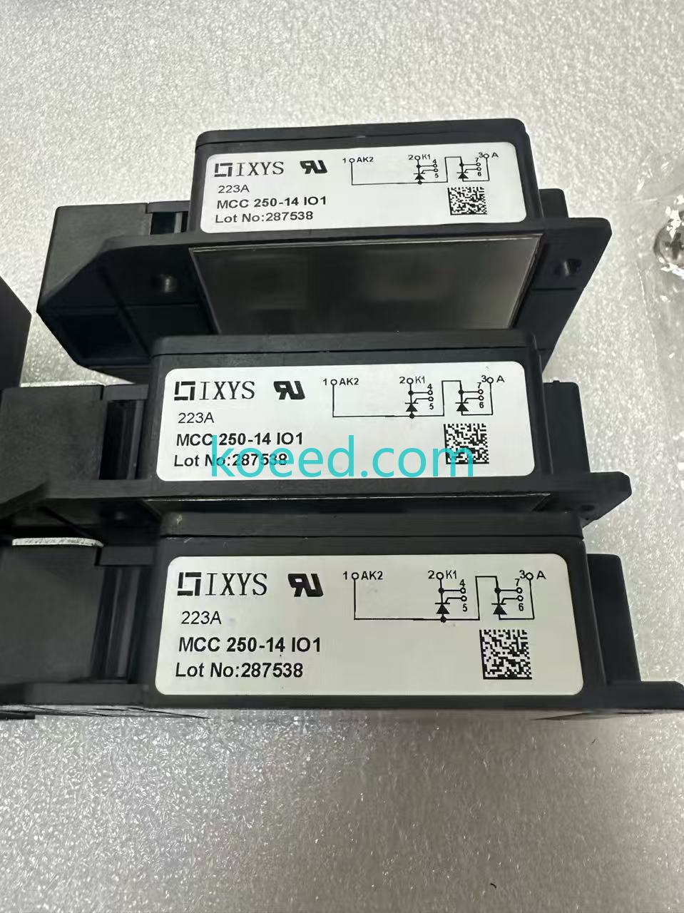
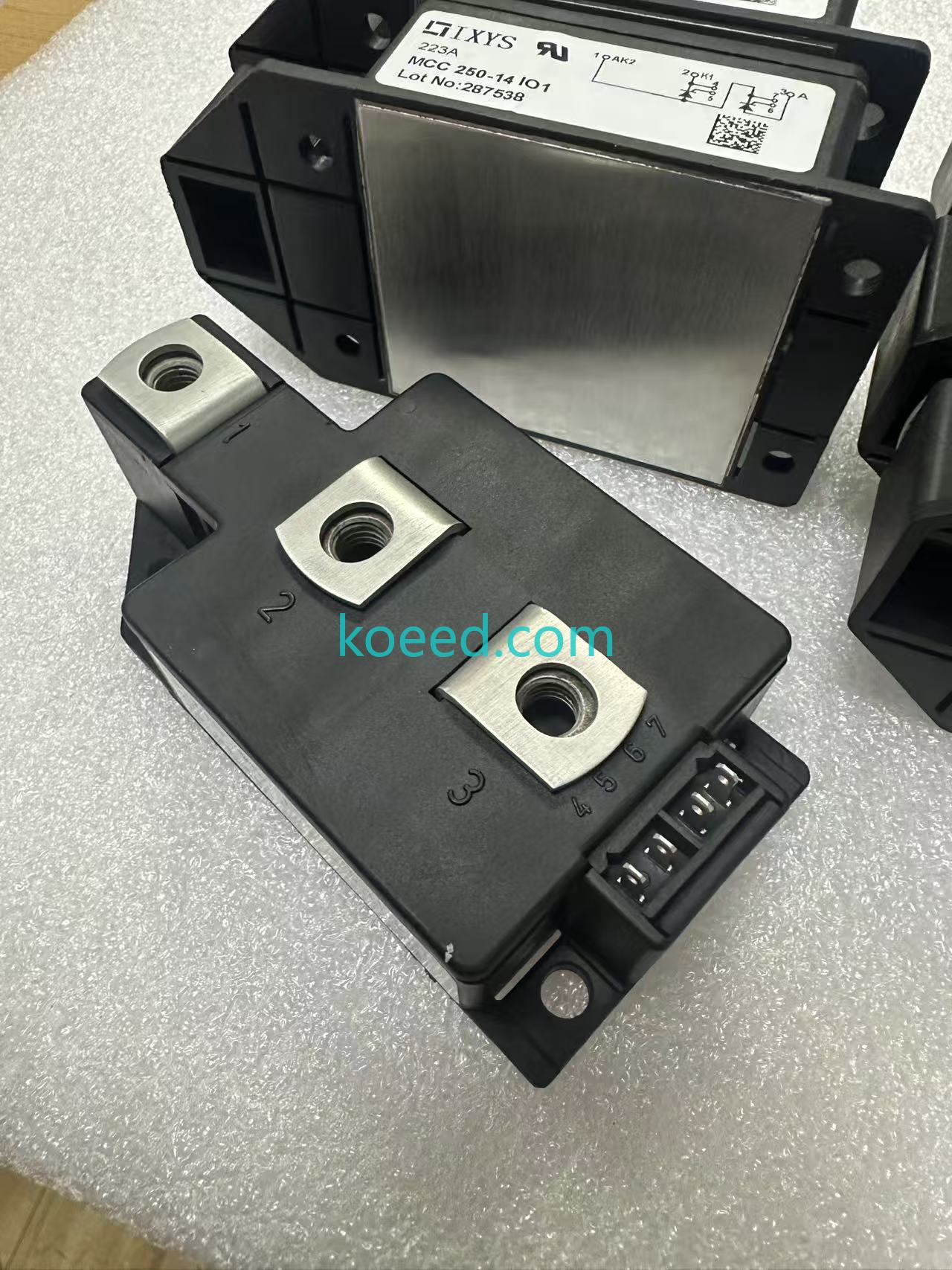
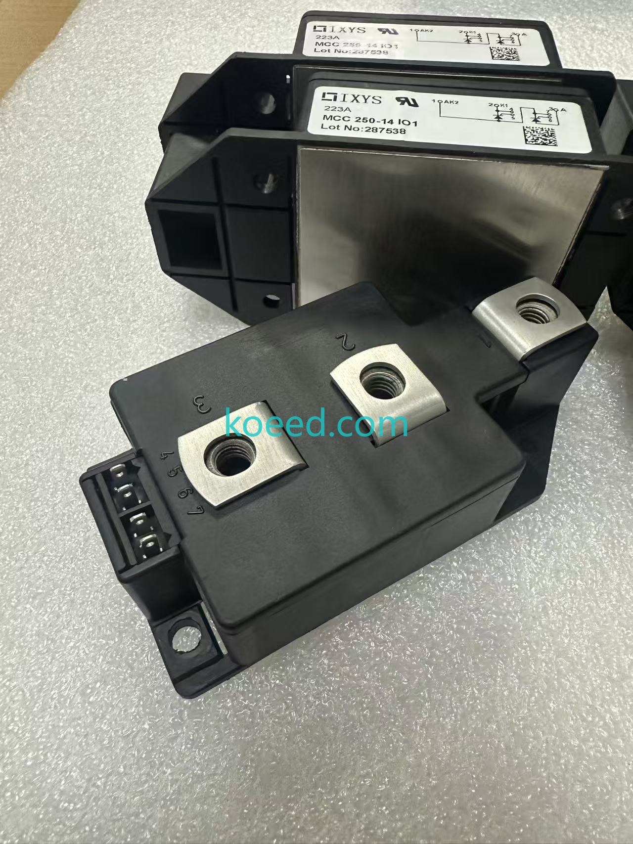
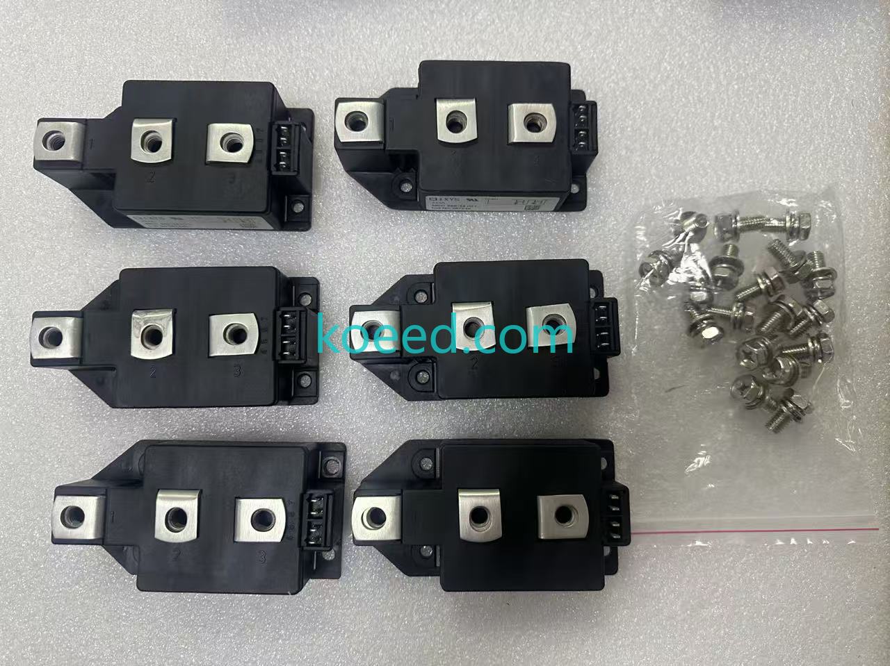
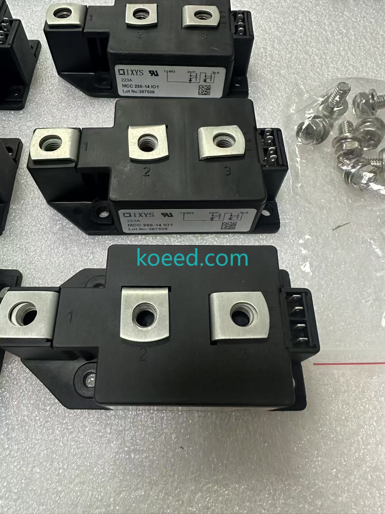
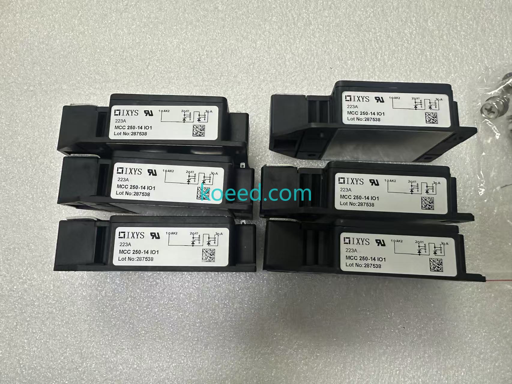
Visual Gallery: MCC250-14Io1 Detailed Inspection
The following gallery provides detailed views of the IXYS MCC250-14Io1 power supply module, showcasing its terminal layout, baseplate construction, labeling, and packaging. Use these images for pre-installation inspection reference and training documentation.
Maintenance & Troubleshooting: Extending Module Life Through 2030 and Beyond
While the MCC250-14Io1 is engineered for rugged industrial environments, maximizing its service life — and avoiding costly unplanned downtime — demands adherence to best practices refined through decades of field experience. Below is the 2026 maintenance playbook.
Preventive Maintenance Schedule
| Interval | Action | Tooling Required |
|---|---|---|
| Monthly | Visual inspection: check for dust accumulation, discoloration, or corrosion on terminals | Flashlight, inspection mirror |
| Quarterly | Torque verification on all power and gate terminal connections (refer to datasheet torque specs) | Calibrated torque wrench |
| Semi-Annually | Thermal imaging scan under full load; verify heatsink thermal compound integrity; measure VT at operating current | FLIR camera, milli-ohmmeter or curve tracer |
| Annually | Full insulation resistance test (gate-to-cathode, anode-to-heatsink); update RUL estimate in asset management system | Megohmmeter (500V DC), asset management software |
Common Failure Modes & Troubleshooting
1. Module Fails to Turn On (No Conduction)
- Symptoms: Zero or intermittent conduction despite gate pulse present.
- Likely Causes: Open gate connection, insufficient gate current (< IGT minimum), or degraded gate-cathode junction.
- Resolution: Verify gate pulse amplitude and duration meet datasheet requirements. For the MCC250-14Io1, typical IGT is approximately 150mA. Inspect gate lead crimps and PCB solder joints in the firing circuit.
2. Thermal Runaway / Overheating
- Symptoms: Case temperature exceeding 100°C under normal load; visible discoloration of housing.
- Likely Causes: Degraded thermal interface material (TIM), insufficient heatsink airflow, loose mounting bolts, or excessive conduction losses due to partial junction degradation.
- Resolution: Remove module, clean both surfaces with isopropyl alcohol, apply fresh thermal paste (recommended: 1.0–1.5 W/m·K minimum), and re-torque mounting bolts in a cross pattern to 5 N·m (or as per mechanical drawing).
3. Spurious Turn-On (dv/dt Triggering)
- Symptoms: Module conducts without gate signal; typically occurs during rapid line voltage transients.
- Likely Causes: Excessive dv/dt across anode-cathode exceeding the module's rated dv/dt (typically 500–1000 V/µs for this class).
- Resolution: Add an RC snubber network directly across the module terminals. Typical values: R = 10–20Ω (10W), C = 0.1–0.47µF (1600V+ rated).
Energy Efficiency & Sustainability: The 2026 Carbon-Accounting Perspective
Sustainability is no longer a marketing checkbox — it is a procurement gatekeeper. The MCC250-14Io1 contributes to your plant's ESG goals in measurable ways:
Conduction Loss Calculation
At 250A average current with a VT of 1.35V, each thyristor dissipates approximately 338W in conduction. With both thyristors conducting in a full-wave configuration, total conduction loss is around 675W. While this is inherent to the silicon physics, selecting the MCC250-14Io1 with its optimized VT specification over a 1.50V competitor saves approximately 75W — or 657 kWh annually in continuous operation. At an industrial electricity rate of $0.12/kWh (2026 global average), that is $79/year per module — compounding significantly across multi-module installations.
End-of-Life Circularity
Littelfuse's continued support for the MCC series through 2026 means that replacement modules are drop-in compatible, eliminating the need for busbar or mechanical redesign. This backward compatibility is a quiet sustainability win — reducing engineering waste and avoiding the carbon cost of re-manufacturing mounting hardware.
Frequently Asked Questions
What is the exact configuration of the MCC250-14Io1 — is it dual thyristor or thyristor/diode?
The MCC250-14Io1 is a dual thyristor module in a series-connected (common-cathode) topology. Both semiconductor elements are identical thyristors, making it ideal for AC phase-control applications such as soft starters and temperature controllers. The "Io1" suffix in IXYS nomenclature indicates the specific internal connection diagram. Always consult the official MCC250-14Io1 datasheet for the precise terminal assignment before wiring.
Can the MCC250-14Io1 be used as a direct replacement for the older MCC250-12Io1?
Yes — with a significant benefit. The MCC250-14Io1 is mechanically and electrically compatible with the 1200V-rated MCC250-12Io1 while offering an additional 200V of blocking margin. This is a drop-in upgrade that enhances system robustness without any mechanical redesign. Always verify that your snubber components are rated for the higher voltage class.
What is the recommended heatsink and mounting torque for this module?
For continuous 250A operation, a forced-air-cooled heatsink with a thermal resistance of ≤ 0.04 K/W is recommended. The mounting bolt torque is typically 5.0 ± 0.5 N·m for M6 hardware (refer to the specific mechanical drawing for your production batch). Uneven torque is a leading cause of premature thermal failure — always use a calibrated torque wrench in a cross-pattern sequence.
Is the MCC250-14Io1 still in active production in 2026?
Yes. Following Littelfuse's acquisition of IXYS, the MCC series remains in active production and is widely available through authorized distributors including Koeed.


