

RY611024 / RY900112 24VDC 8A SPDT Power Relay - 2026 Industrial Automation & ROI Guide
Strategic Overview: RY611024 / RY900112 24VDC 8A SPDT Power Relay in 2026
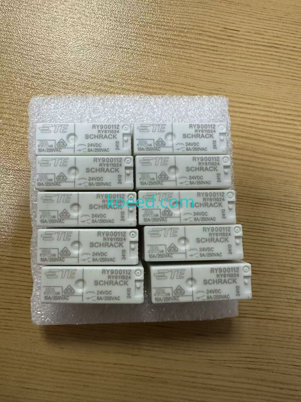
The TE Connectivity SCHRACK RY611024, cross-referenced under companion part number RY900112, is a general-purpose electromechanical power relay built around a 24 VDC coil and a 1 Form C (SPDT) 8 A contact set. As industrial panels move toward denser I/O, smarter edge gateways, and tighter energy budgets in 2026, this relay remains the dependable interposing layer between low-power PLC/controller outputs and higher-current field loads such as solenoid valves, contactors, indicator banks, motor starters, and HVAC actuators.
Rather than treating the relay as a commodity, forward-looking integrators now view it as a sensor node for predictive maintenance: a physical switching point whose coil behavior and contact health can be trended by modern smart I/O racks.
Why the RY611024 Fits the 2026 Automation Stack
IT/OT Convergence and Interposing Role
In converged architectures, PLC transistor outputs (24 VDC) rarely drive field loads directly. The RY611024 sits in the middle, converting a low-current logic signal into a galvanically isolated, high-current switching action. Its SPDT (NO/NC) form gives control engineers a spare contact path for feedback, HMI status lamps, or safety interlocks without adding a second relay.
Sustainability and Energy Efficiency
With a coil power rating of approximately 245 mW, the RY611024 draws a fraction of the 1 W+ consumed by legacy general-purpose relays. Across a 500-point panel, that delta translates into measurably lower enclosure heat, reduced cooling load, and a smaller carbon footprint per installed cabinet, a key line item in 2026 ESG reporting.
ROI and Total Cost of Ownership
- Lower energy cost: Ultra-low coil holding power reduces continuous electrical spend.
- Reduced thermal stress: Cooler panels extend the life of neighboring electronics and cabling.
- Fewer SKUs: The 8 A / 250 VAC rating covers most interposing and control duties, simplifying spares inventory.
- Predictive visibility: Coil-current monitoring on smart I/O enables early detection of contact degradation before unplanned downtime.
Technical Benchmarking and Specifications
The table below consolidates the key electrical and mechanical parameters engineering teams rely on for panel design and replacement sourcing.
| Parameter | RY611024 (RY900112) Specification |
|---|---|
| Manufacturer | TE Connectivity (SCHRACK) |
| Relay type | General Purpose Power Relay, Monostable DC |
| Contact arrangement | 1 Form C (SPDT - NO/NC) |
| Contact current rating | 8 A |
| Coil voltage | 24 VDC |
| Coil resistance | approximately 2,350 ohm |
| Coil power | approximately 245 mW (Class F insulation system) |
| Max. contact voltage | 250 VAC (400 VAC peak withstand class) |
| Termination | 5-pin solder / through-hole |
| Mounting | PCB / chassis mount |
Legacy Relay vs RY611024 - 2026 Upgrade Case
| Attribute | Legacy General Relay (pre-2020) | RY611024 (2026 Optimized) |
|---|---|---|
| Coil consumption | approx. 1.0 W typical | approx. 245 mW |
| Insulation system | Class B common | Class F |
| Contact rating | 5-6 A typical | 8 A (SPDT) |
| Predictive maintenance support | None | Coil/contact trendable via smart I/O |
| Panel thermal footprint | Higher | Low - reduced cooling load |
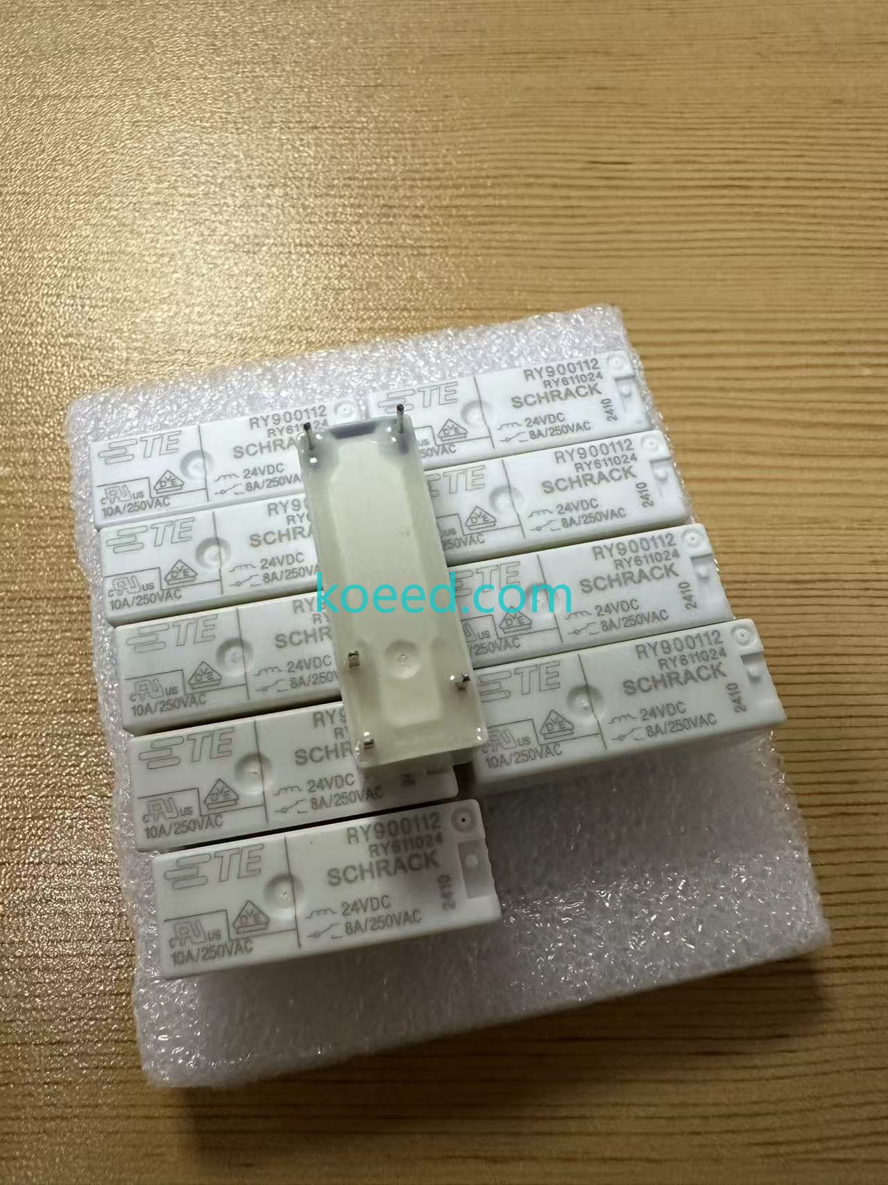
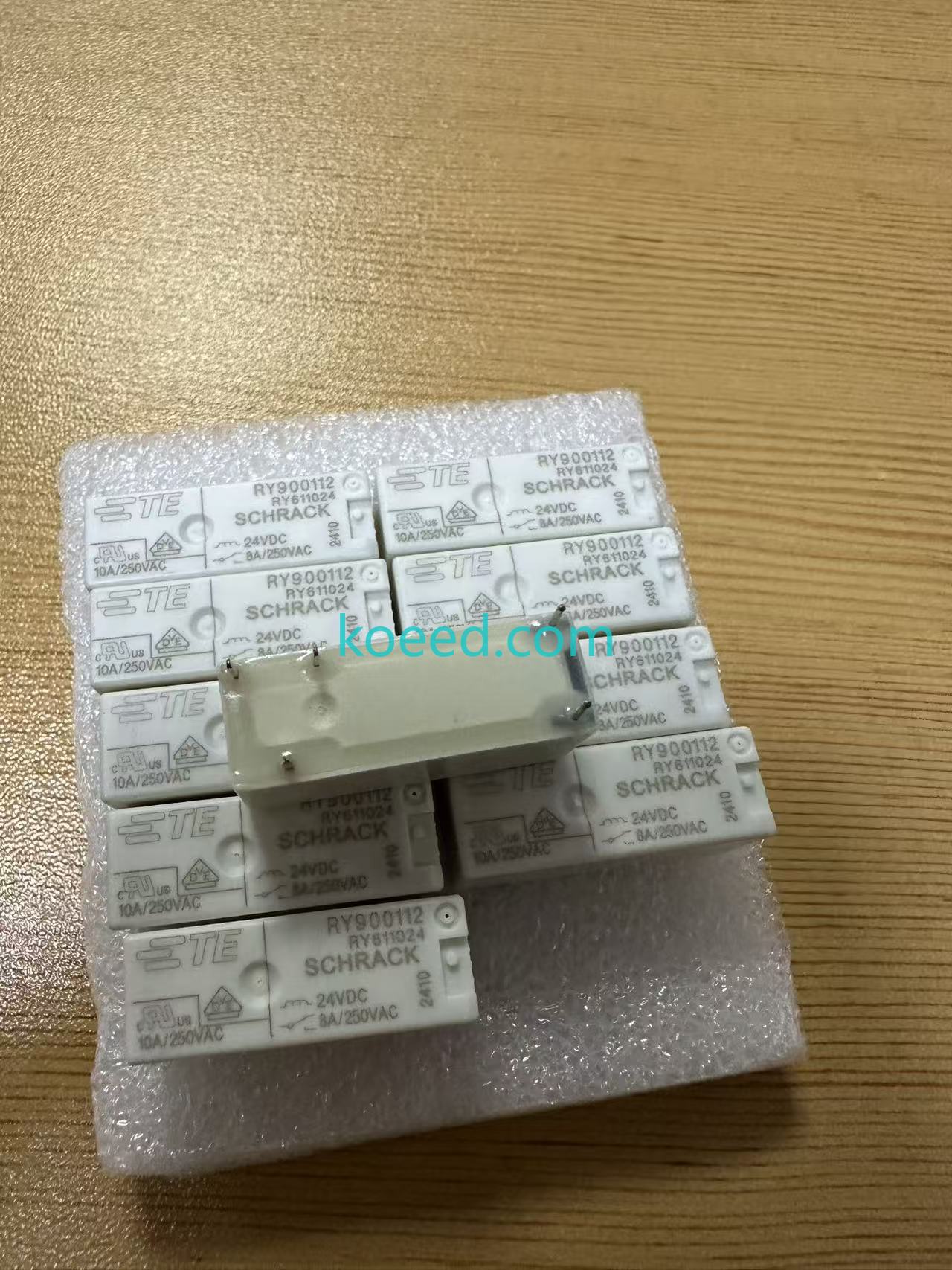
Visual Gallery
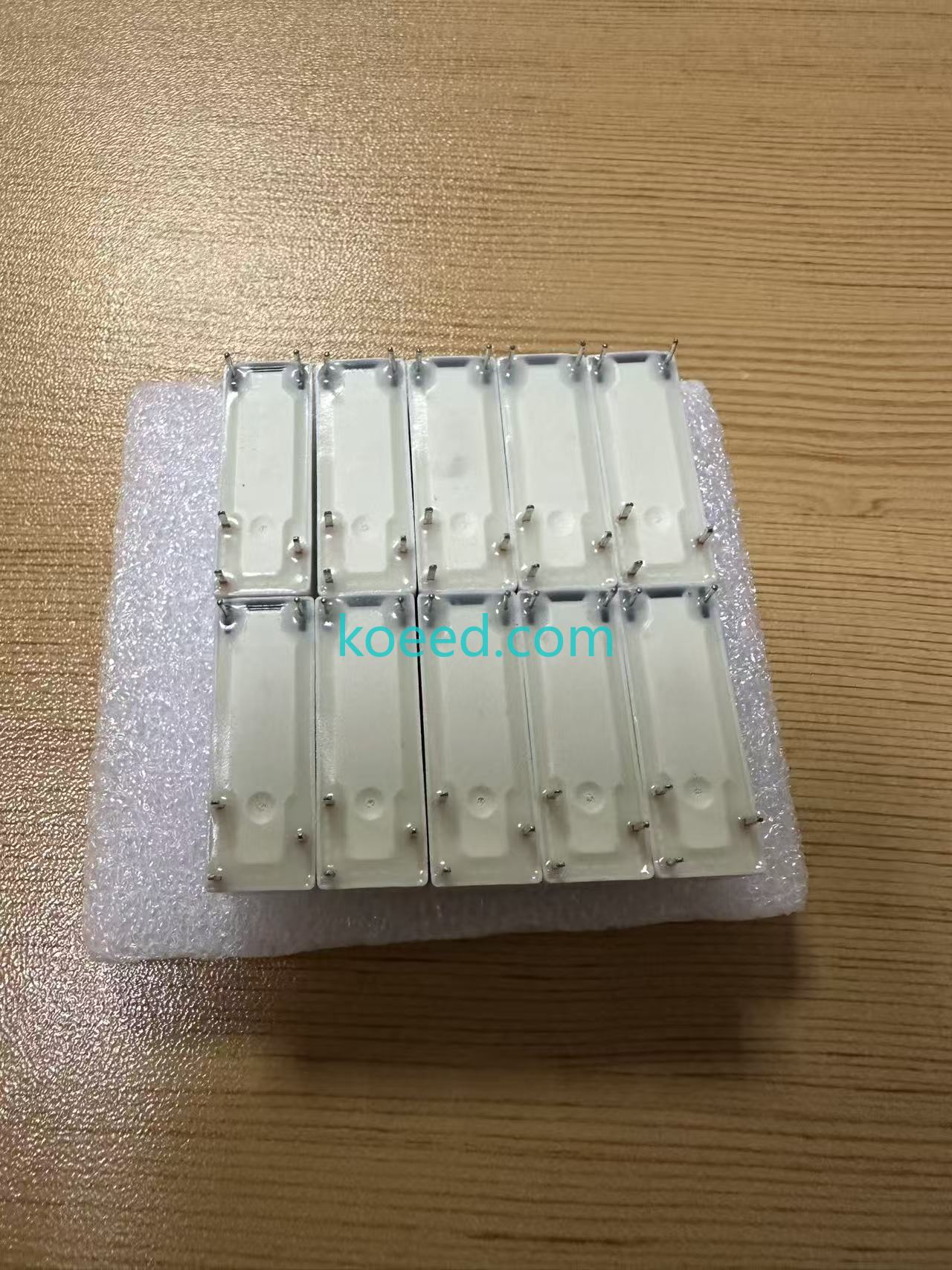
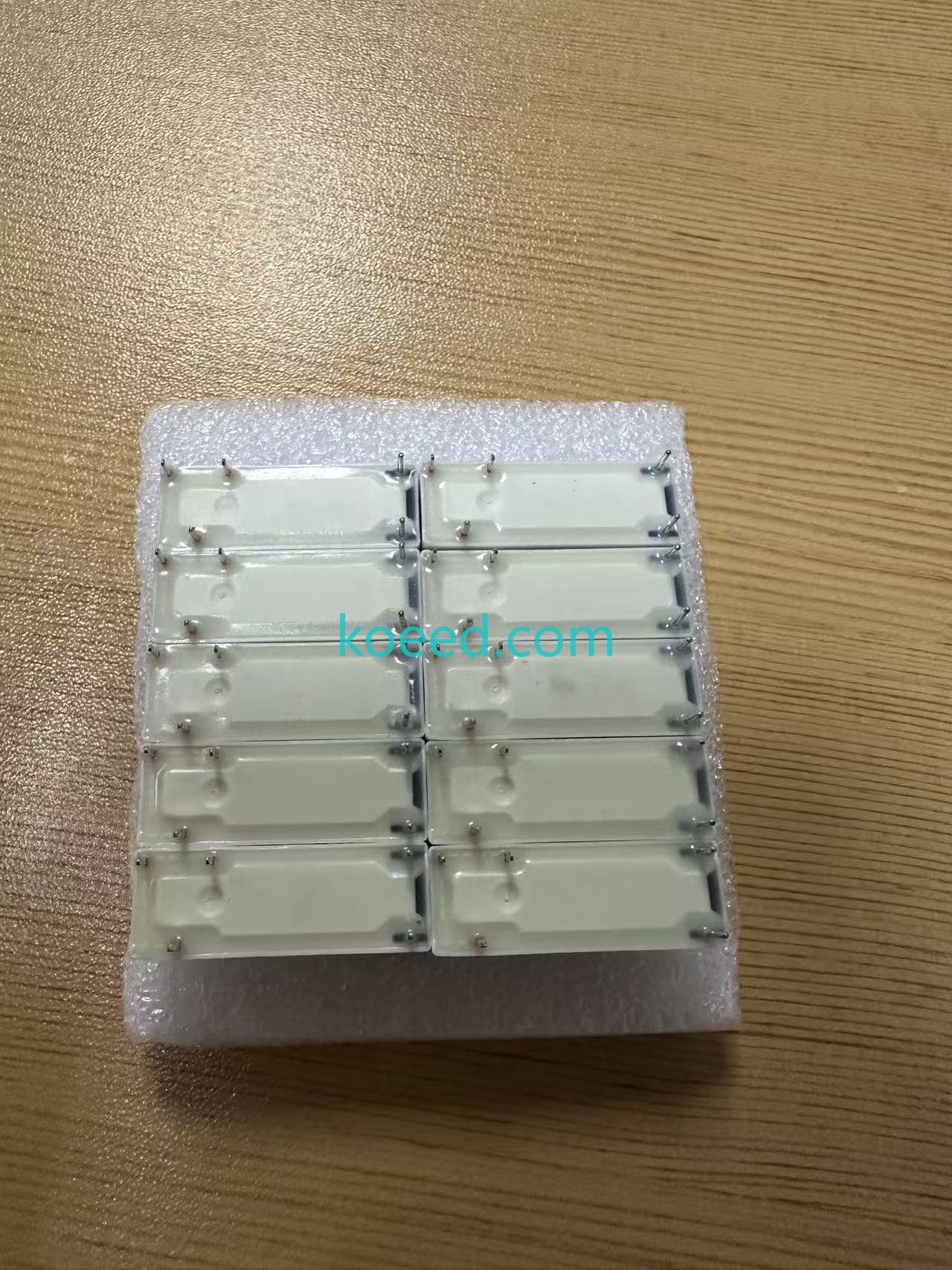
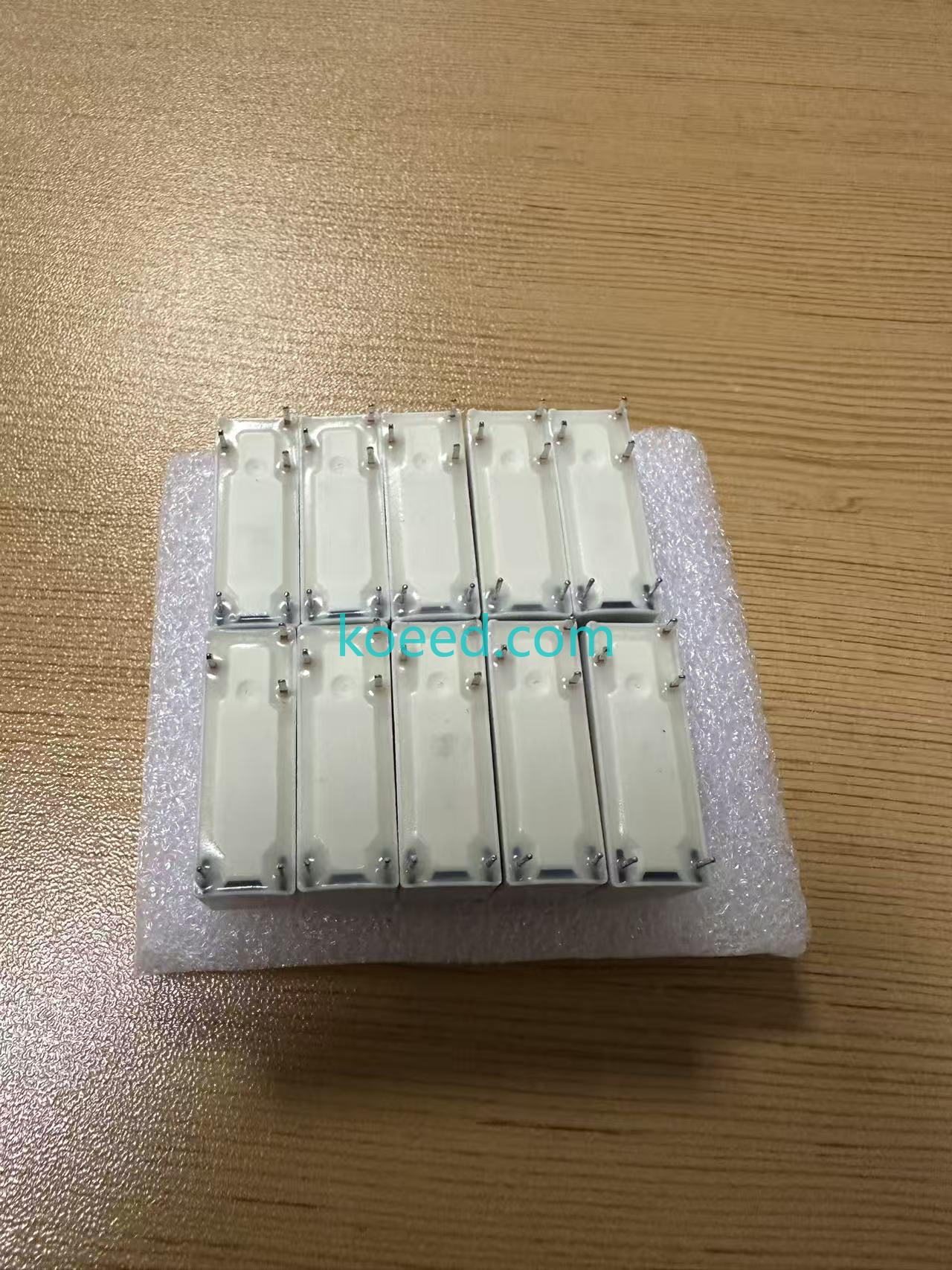
Reference imagery of the RY611024 / RY900112 power relay - terminal layout, coil side, and contact configuration.
Maintenance and Troubleshooting for Longevity
Predictive Maintenance Practices
- Coil-current trending: A gradual rise in coil current can signal increased mechanical friction or a degrading coil before hard failure.
- Contact resistance checks: Measure contact voltage drop under load periodically; rising resistance indicates contact pitting or contamination.
- Switching-count logging: Pair with smart I/O to log operations and schedule replacement against mechanical endurance limits.
- Thermal imaging: A hot relay relative to its neighbors often indicates contact overload or poor termination.
Common Fault Symptoms and Resolutions
| Symptom | Probable Cause | Corrective Action |
|---|---|---|
| Coil does not pick | Low or missing 24 VDC, voltage drop | Verify supply at coil terminals; check wiring and driver output |
| Contact chatter / buzzing | Unstable coil voltage or AC ripple | Stabilize DC supply; add suppression diode |
| Welded / stuck contacts | Inrush current beyond rating | Add snubber or re-rate load; verify 8 A limit |
| Premature contact wear | Arcing without suppression | Fit RC snubber (AC) or diode (DC) across load |
Frequently Asked Questions
What is the difference between RY900112 and RY611024?
Both designations refer to the same 24 VDC, 8 A, SPDT (1 Form C) power relay family. RY611024 is the primary TE Connectivity SCHRACK part number, while RY900112 is a widely used companion/cross-reference number for sourcing and ordering.
Is this relay suitable for PLC interposing?
Yes. The 24 VDC coil matches standard PLC transistor outputs, and the 8 A SPDT contact set comfortably drives solenoids, contactors, and indicator loads.
What is the maximum contact current?
The contact rating is 8 A with a maximum contact voltage of 250 VAC (400 VAC peak class).
Can it switch both AC and DC loads?
Yes. The 1 Form C (SPDT) configuration supports both NO and NC paths, switching AC or DC loads within the rated current/voltage limits.
Do I need a flyback diode on the coil?
For 24 VDC coil circuits, a flyback diode across the coil is strongly recommended to suppress back-EMF and protect the driving PLC output. For inductive DC loads, install a diode across the load coil as well.
Need a Quotation or Technical Cross-Reference?
Contact us for bulk pricing, replacement sourcing, and panel design support.


