

HGM6110N Generator Controller: Advanced PLC Automation for Diesel Generator Sets
On this page
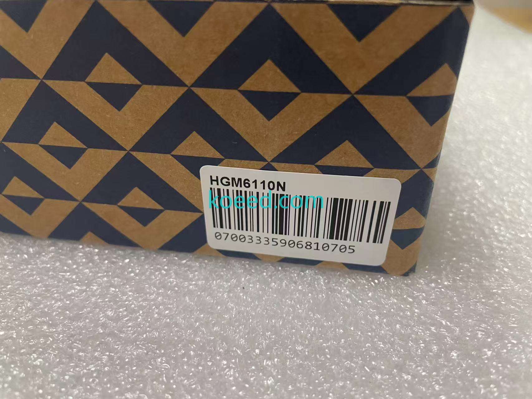
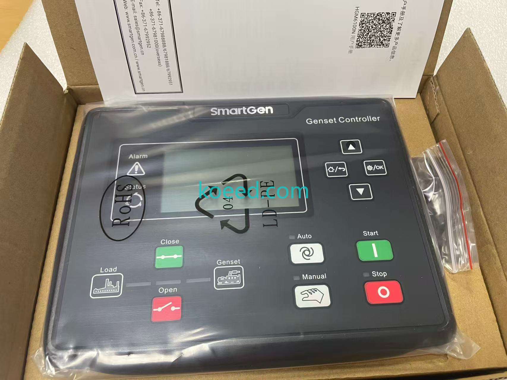
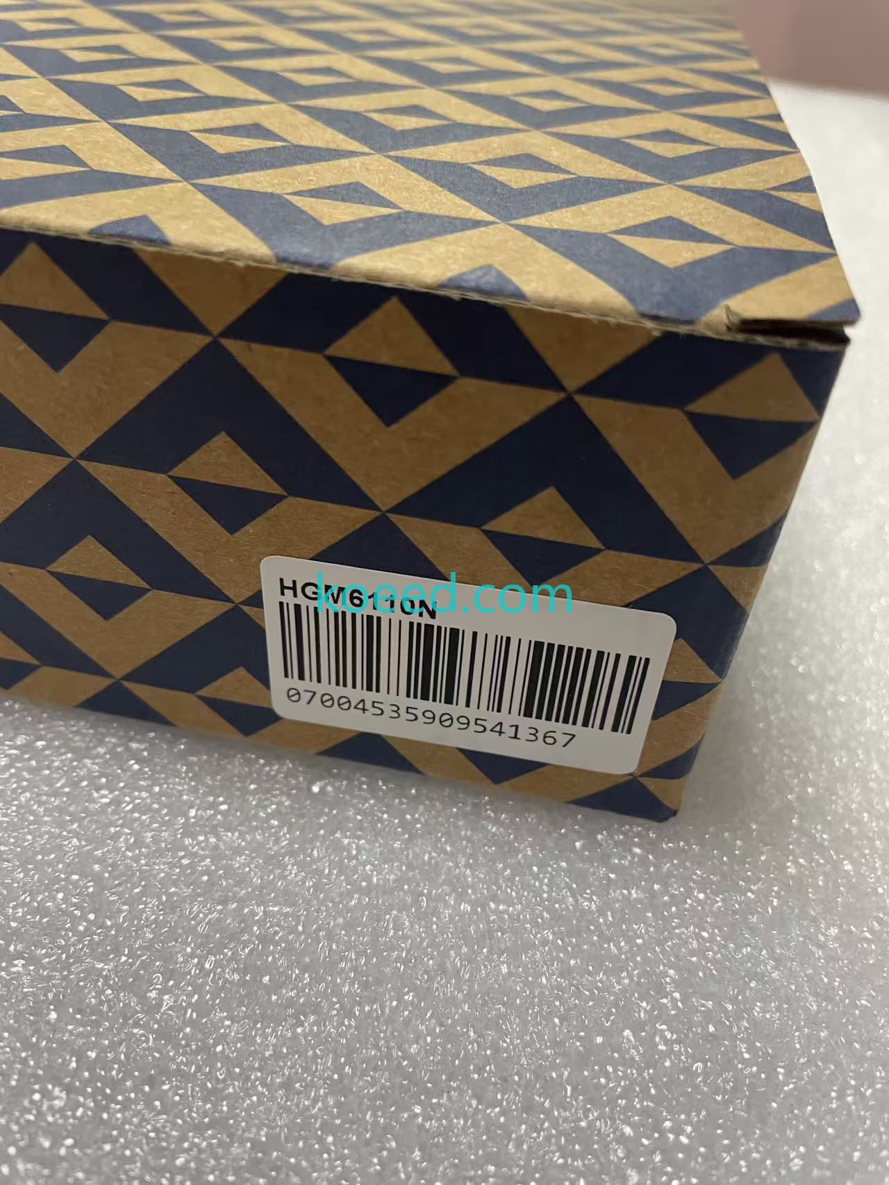
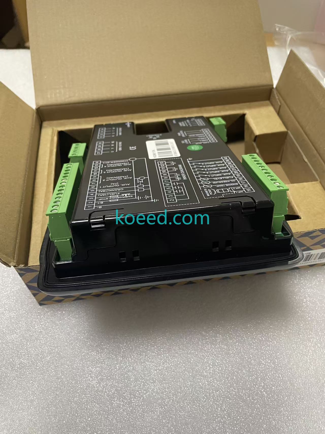
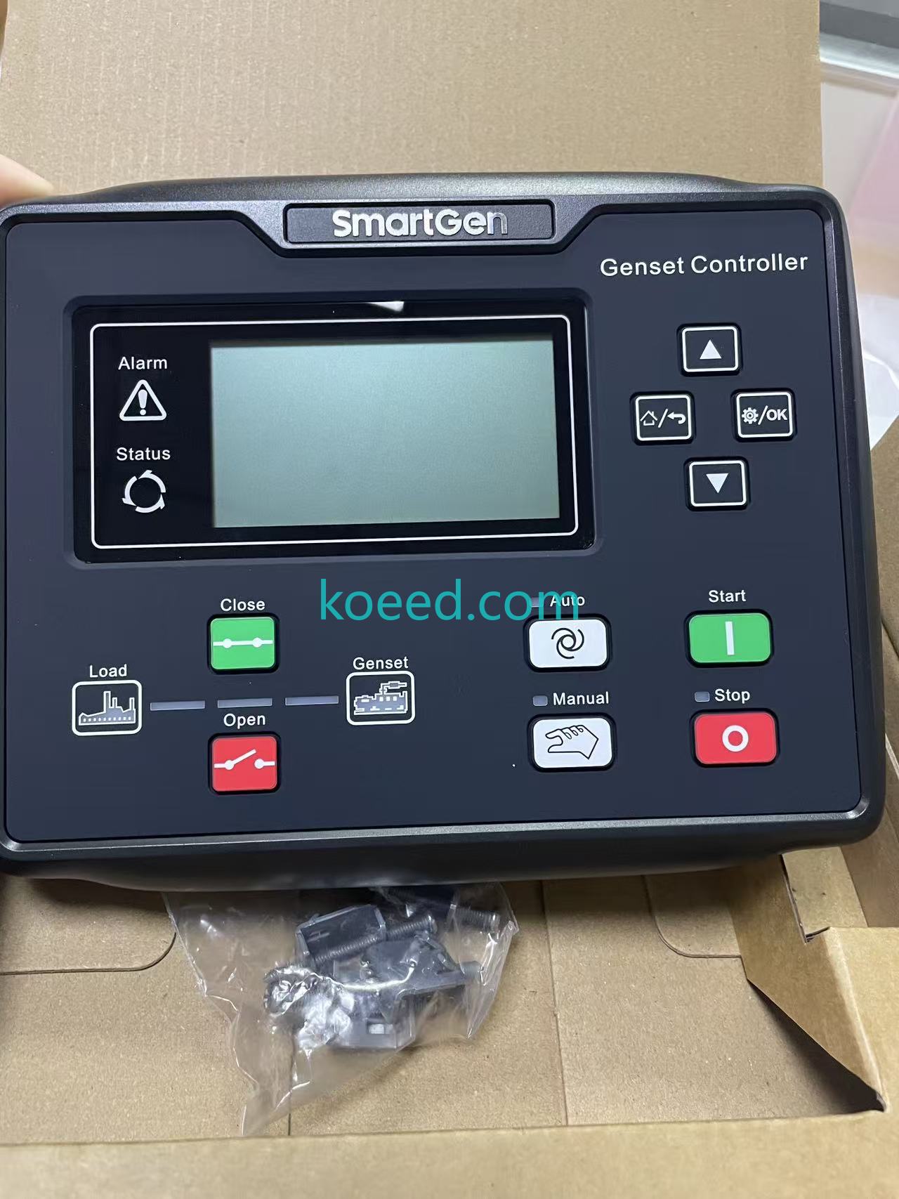
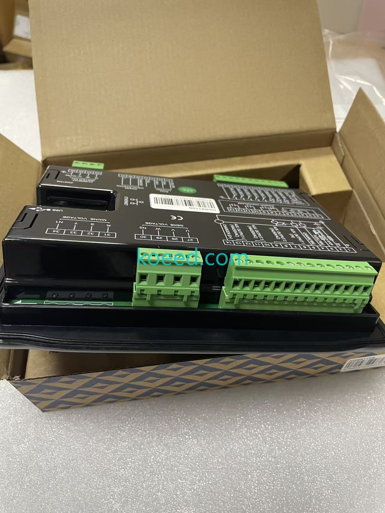
What this delivery is: two SmartGen HGM6110N genset controllers — the automatic-start diesel generator control modules with LCD and CAN (J1939) support — brand new in SmartGen's current geometric-pattern cartons, bought in two separate orders (2025-12-22, original with one-year warranty; 2026-03-09, new), uploaded across those dates. Each unit carries its own barcode — 07003335906810705 and 07004535909541367 — and each arrived with the fascia film still on, the gasket, mounting clamps and screws bagged, and the packing slip with SmartGen's Zhengzhou address and the user-manual QR code inside the box.
Reading the controller
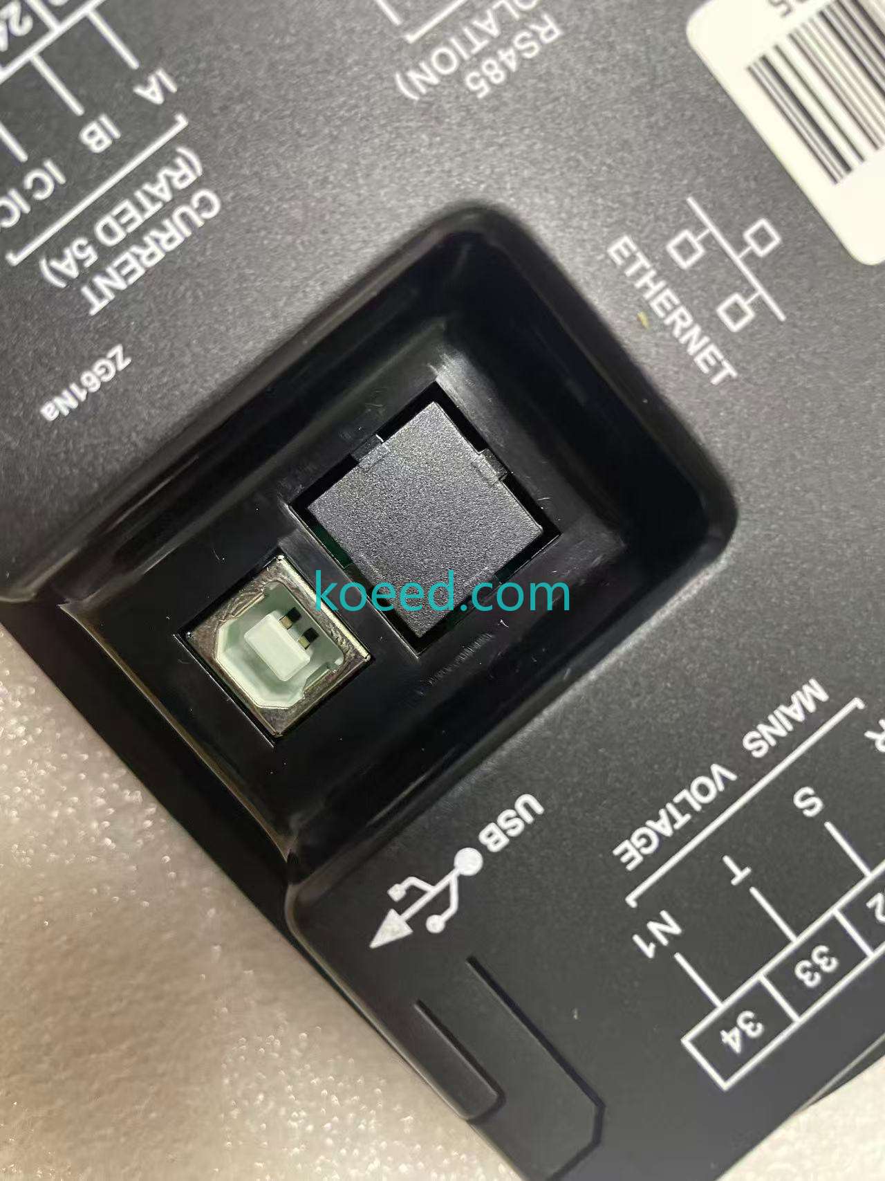
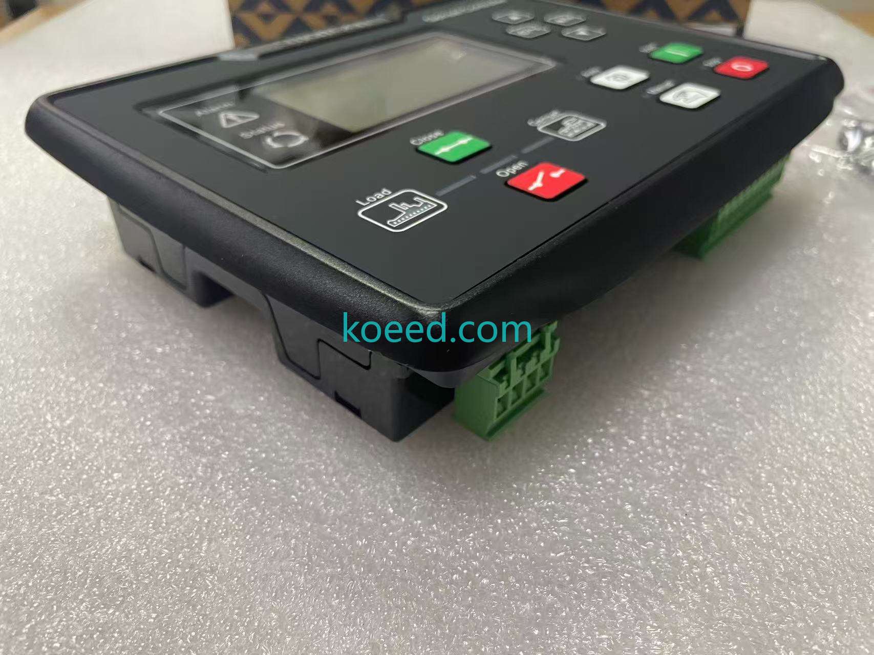
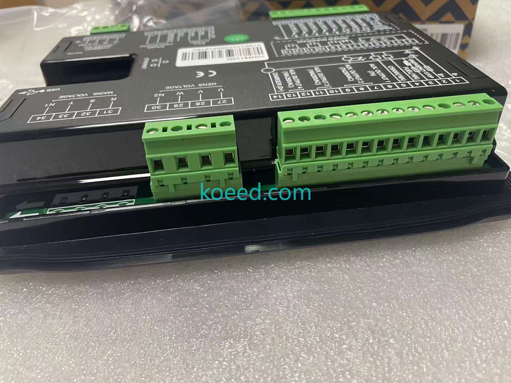
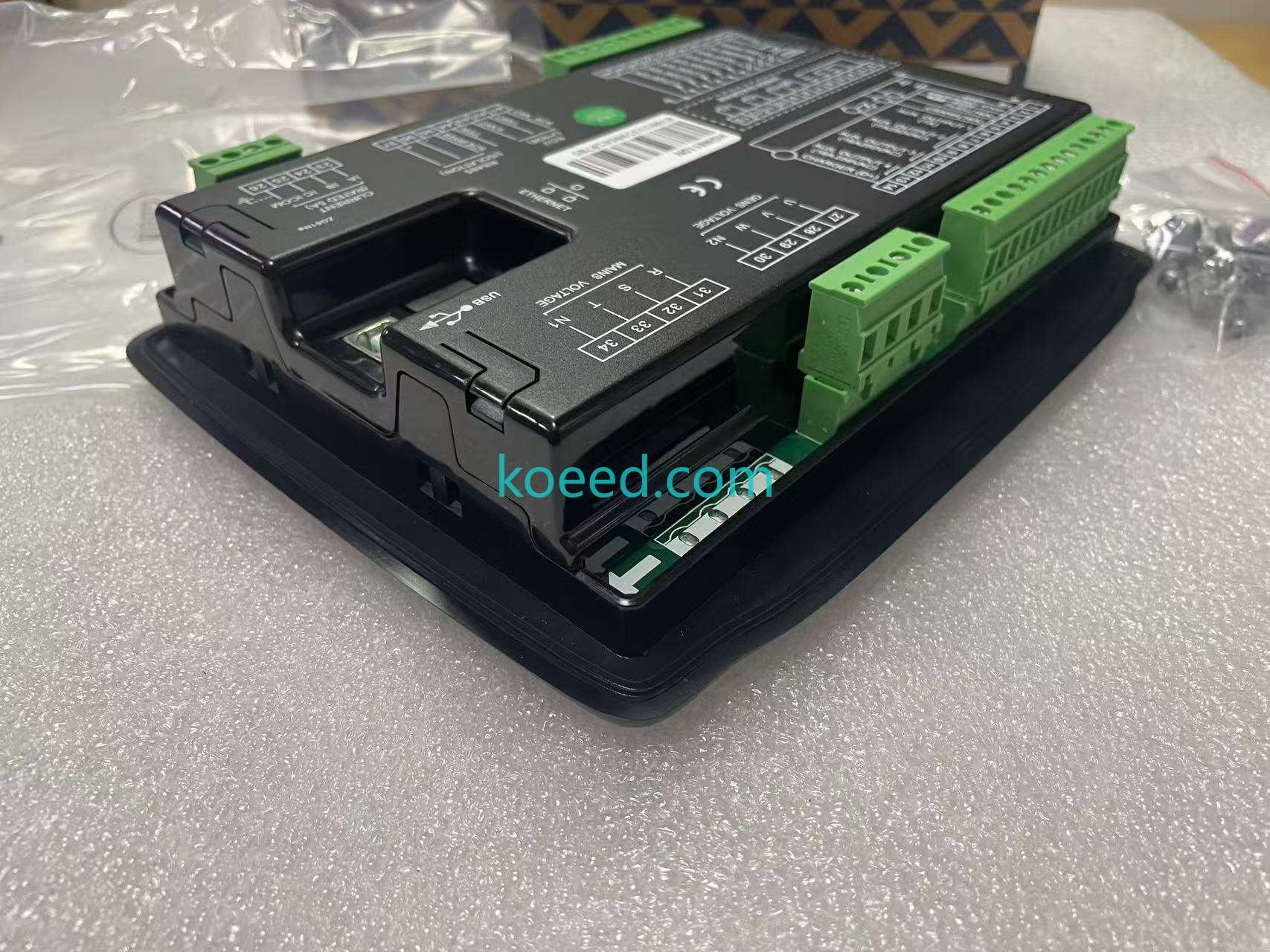
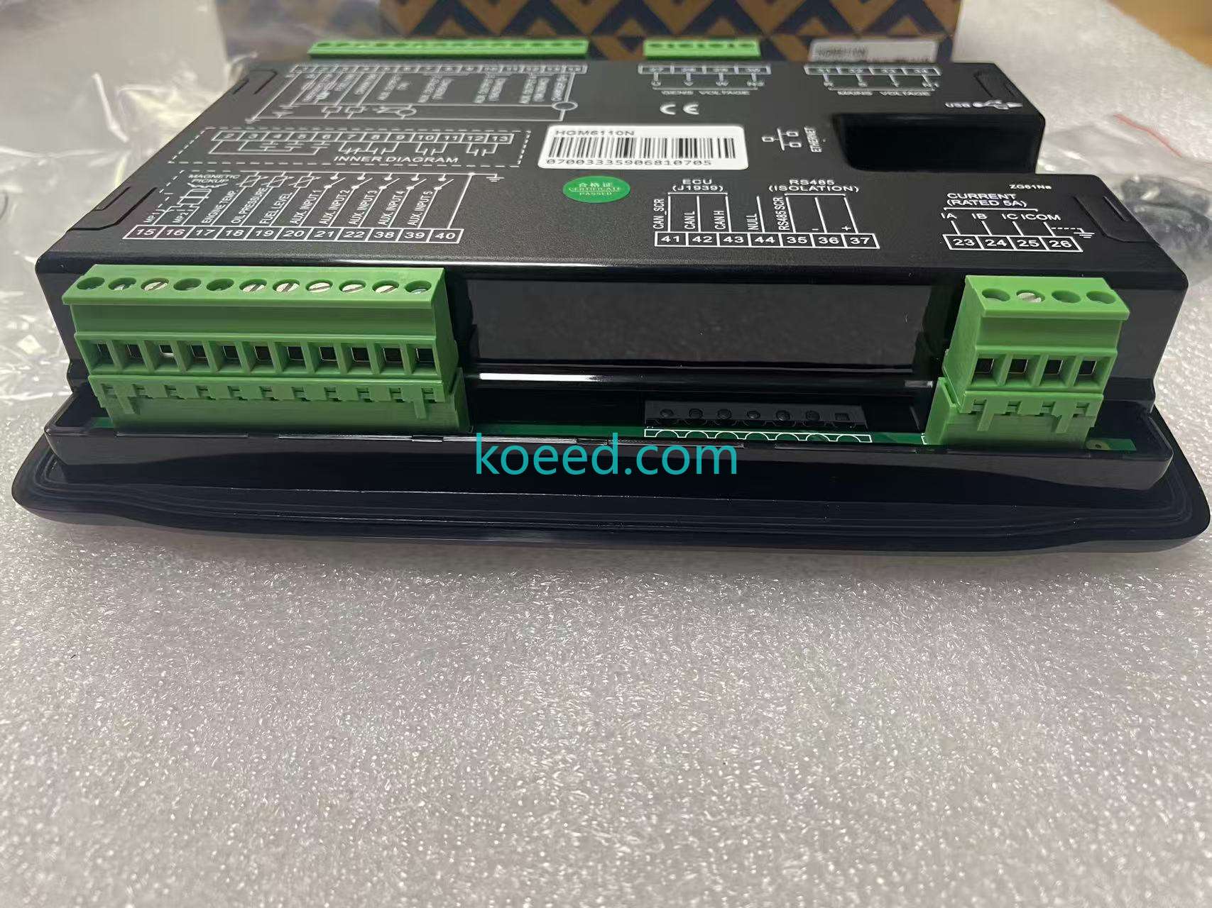
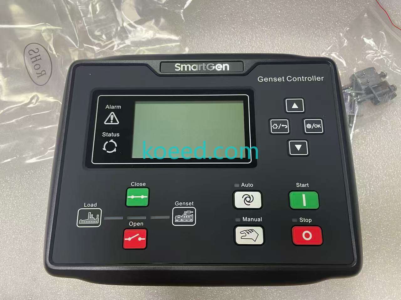
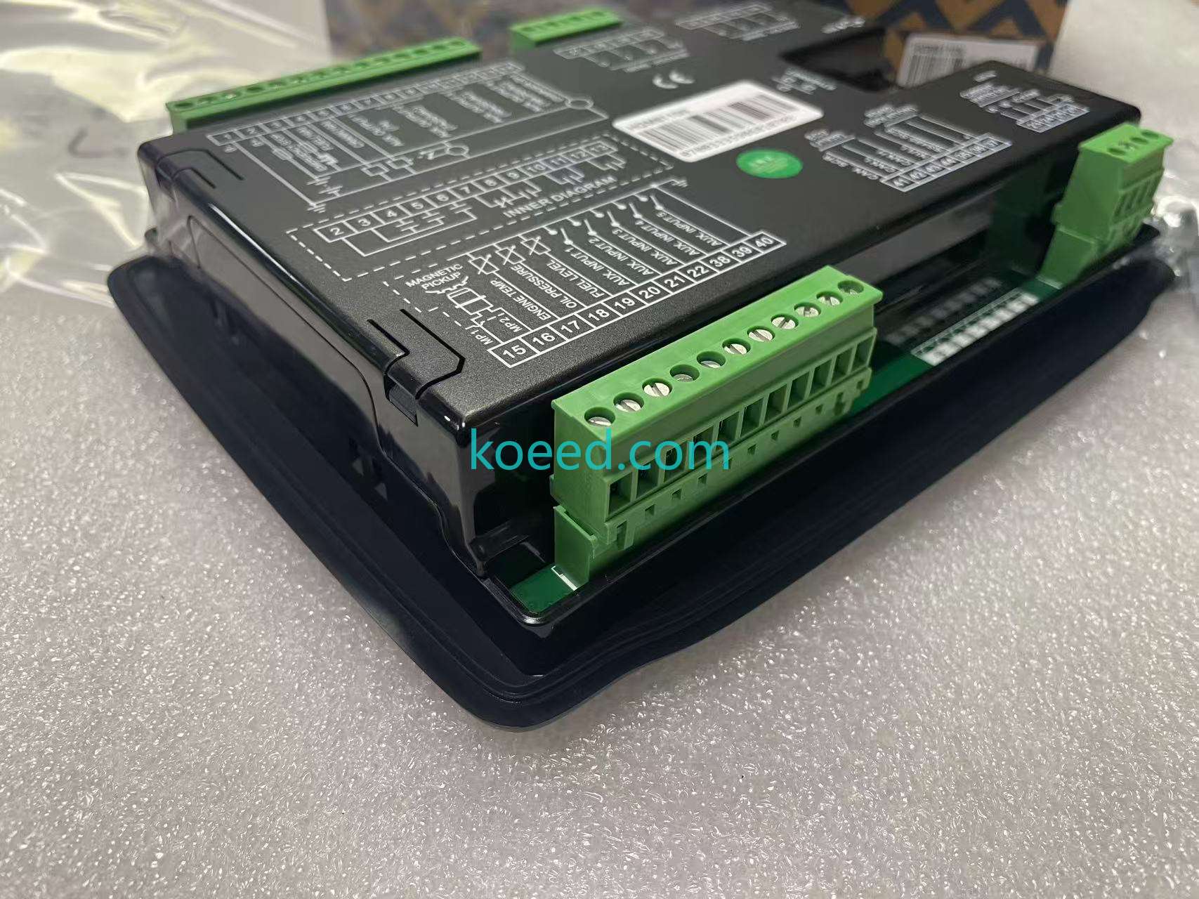
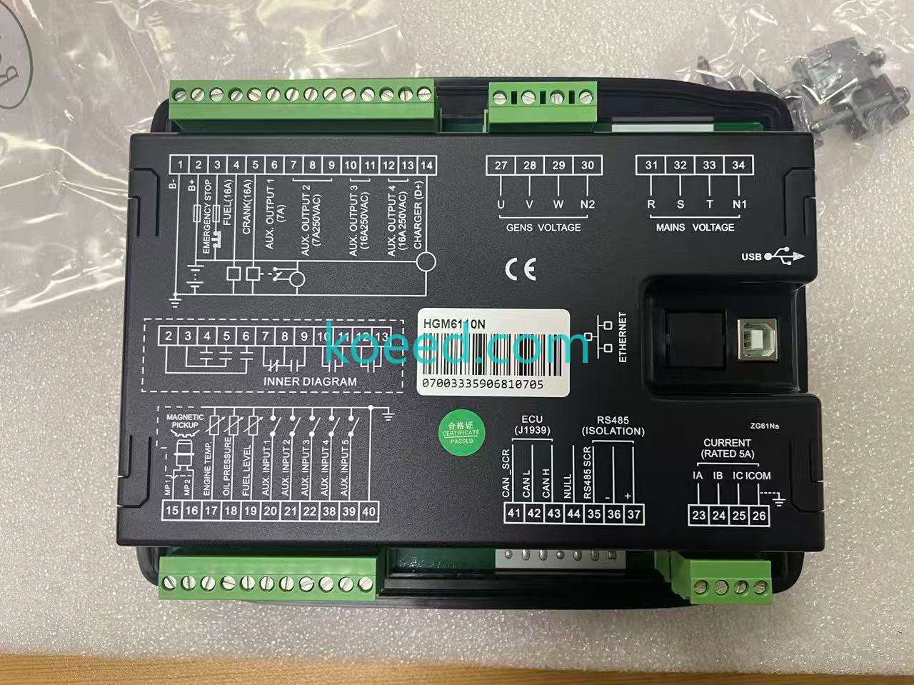
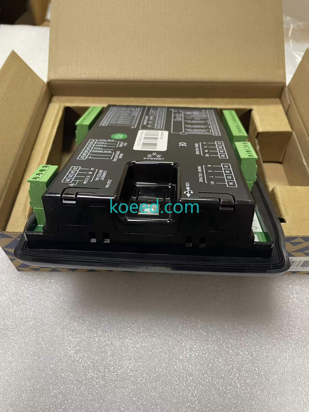
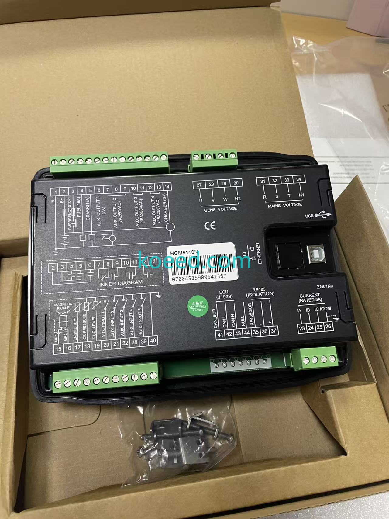
The HGM6110N is SmartGen's single-genset automatic start controller: it cranks and releases the engine, watches mains and genset voltages, and drives the genset breaker through the big green Close and red Open buttons that sit under the Load→Genset flow graphic on the fascia. The panel carries an LCD with Alarm and Status indicators, navigation up/down arrows with Home/Return and Setup/OK keys, and the Auto and Manual mode buttons beside Start and Stop. The terminal legend on the rear is the full engineering map: battery in at 1 B- and 2 B+, emergency stop at 3, fuel and crank outputs at 4 (16 A) and 5 (16 A), four programmable auxiliary outputs at 6–9 (7 A; 7 A/250 VAC; 16 A/250 VAC; 16 A/250 VAC), charger D+ monitoring at 12, genset sensing U/V/W/N2 at 27–30, mains sensing R/S/T/N1 at 31–34, and the CT current inputs IA/IB/IC/ICOM at 23–26 rated 5 A. Sensor inputs run magnetic pickup MP1/MP2 at 15/16, engine temperature at 17, oil pressure at 18 and fuel level at 19, with five configurable auxiliary inputs at 20/21/22/38/39-40. Communications are the N-variant's headline: ECU (J1939) CAN bus at 41–44 (CAN_SCR, CANL, CANH, NUL), isolated RS485 at 35–37, plus Ethernet and a USB port behind the rear recess. An INNER DIAGRAM silkscreen, the CE mark and a green 合格证/CERTIFICATE PASSED disc complete the rear; the current-input legend prints as CURRRENT (RATED 5A) with a triple R — factory silkscreen spelling, reported as printed.
| Item | Value on the case / in the record |
|---|---|
| Product | SmartGen HGM6110N automatic start genset controller (LCD, CAN J1939) |
| Panel | LCD + Alarm/Status; arrows, Home/Return, Setup/OK; Load-Close/Open-Genset graphics; Auto/Manual, Start (green), Stop (red) |
| Power / outputs | 1 B-, 2 B+; 3 EMERGENCY STOP; 4 FUEL 16A; 5 CRANK 16A; 6-9 AUX.OUTPUT1-4 (7A / 7A-250VAC / 16A-250VAC / 16A-250VAC); 12 CHARGER (D+) |
| Sensing | 27-30 GENS U/V/W/N2; 31-34 MAINS R/S/T/N1; 23-26 IA/IB/IC/ICOM current inputs rated 5 A; 15/16 magnetic pickup; 17 engine temp; 18 oil pressure; 19 fuel level |
| Programmable inputs | AUX.INPUT1-5 at 20, 21, 22, 38, 39-40 |
| Communications | ECU (J1939) CAN 41-44; RS485 isolated 35-37; Ethernet; USB (rear recess) |
| Unit serials | Barcodes 07003335906810705 and 07004535909541367; mould marks ZG61NB and ZG61Na |
| Factory print quirk | CURRRENT (RATED 5A) silkscreen spelling as printed |
| Condition / quantity | New in boxes with film, gaskets and fixing kit; 2 pcs from two orders (2025-12-22 original, 2026-03-09) |
Commissioning notes
Wire the battery directly to 1/2 with the emergency stop loop closed, put the CTs on the genset output with IA/IB/IC on the phases and ICOM as the common return, and take mains and genset sensing from the contactor sides — the controller needs to see both to decide the transfer. The five auxiliary inputs and four outputs cover the usual rig: remote start, low-fuel lockout, a fan or damper drive on AUX.OUTPUT3, a fault relay on AUX.OUTPUT4. J1939 is the reason to pick the N variant for an electronic engine: the CAN pair at 42/43 replaces the oil-pressure and temperature senders on a compliant ECU, and the controller reads real engine data instead of analog approximations. Parameters live behind Setup/OK, and the USB port or Ethernet handles firmware and monitoring from a laptop. For the smaller sibling in the same family, the storefront lists the HGM6120N, and a genset build usually adds SmartGen's battery charger — the BAC06A-24V/3A listing pairs with this controller's CHARGER (D+) input.
Photos
Inspection video.
Second inspection video.

Related products on KOEED
The same controller on the storefront: HGM6110N controller. Family and companions: the HGM6120N sibling and the BAC06A-24V/3A battery charger.
Need an HGM6110N from this pair, the HGM6120N instead, or a wiring review for your genset panel? Send the engine type — we confirm stock and fitment with photos.
Request a quoteNeed a quote for this part?
Send us the part number or article link — we will confirm price, availability and lead time.


