

FANUC A660-2004-T411 Teach Pendant Cable (10M) | 2026 RJ3 / RJ3iB Integration & Retrofit Guide
Component: FANUC A660-2004-T411 — Teach Pendant Connection Cable, 10 m
System Class: RJ3 / RJ3iB robot controllers & pendant interfaces
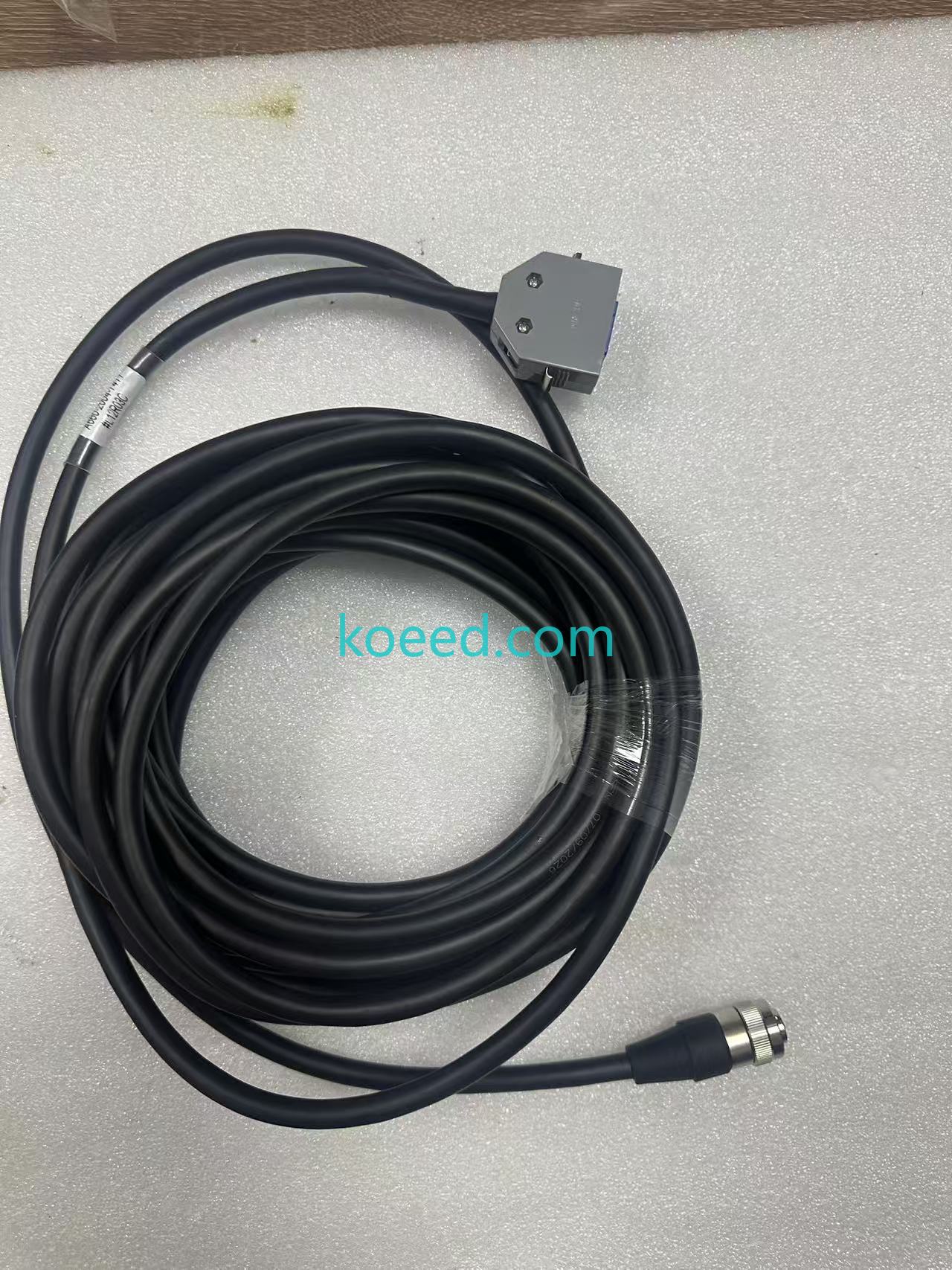
Architecture: 20-pin MR-style shielded assembly, oil-resistant industrial jacket
2026 Relevance: Aftermarket lifecycle extension for the still-active RJ3 install base
Full stock, imagery and expedited shipping options are available on the Koeed product page: 1PC FANUC A660-2004-T411 Teach Pendant Cable — A6602004T411.
1. Strategic Overview: Why a 10-Metre Cable Is a 2026 Business Decision
In 2026, the average FANUC RJ3-class robot cell is somewhere between its 18th and 25th year of service. These controllers were never designed for a 25-year horizon — yet they remain in production because the alternative (a full controller migration to R-30iB Plus) carries a six-figure capital burden per line. The result is a sprawling legacy-as-strategy install base, and the humble teach pendant cable sits at its most fragile single point.
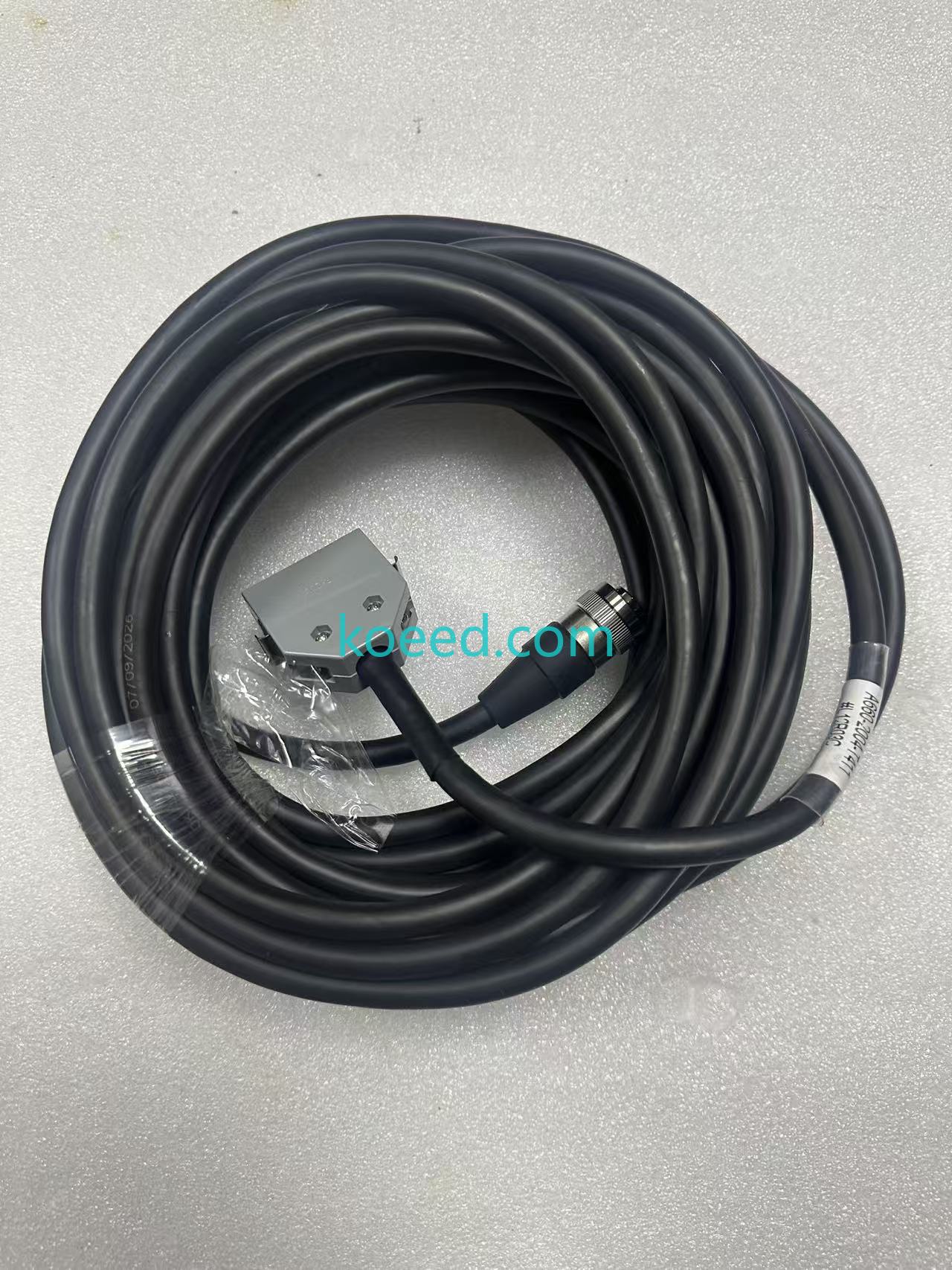
The FANUC A660-2004-T411 is the 10-metre interconnect between the pendant and the controller pendant interface. It is not a generic patch lead. It carries high-density logic signals plus dual-channel enable-switch (deadman) returns inside a single shielded assembly, and it is expected to survive continuous flexing on a moving pendant hook, coolant mist, and the electrical noise of a welding or machining cell.
The 2026 forces reshaping pendant cabling demand
- IT/OT convergence: Even legacy RJ3 cells are now instrumented. Cable integrity directly affects the reliability of the serial/i-Link data stream feeding MES, historians and OEE dashboards. A marginal shield ground shows up as phantom communication faults that OT teams misdiagnose as network problems.
- TCO over CapEx: A verified cable is a fraction of the cost of a controller retrofit, and fraction again of one hour of unplanned line downtime in an automotive or tier-one plant.
- Sustainability: Extending the service life of a robot arm, controller enclosure and cabling harness avoids the embodied carbon of new hardware. Cable-level repair is one of the lowest-carbon interventions available in a factory.
- Predictive maintenance: Pendant cables fail progressively — intermittent shield faults, then resistance creep in the enable loop, then hard failure. Baselines taken today become the trend data that triggers a pre-emptive replacement tomorrow.
2. Technical Benchmarking: A660-2004-T411 Under the Spotlight
Numbers matter more than adjectives in a maintenance spare-parts decision. The table below benchmarks the unit against the failure modes most commonly seen on ageing RJ3 hardware, and against the two most frequent field substitutions.
| Parameter | A660-2004-T411 (OEM-Spec) | Generic Pendant Cable | Field-Splice / Repair |
|---|---|---|---|
| Part Number | A660-2004-T411 | Unbranded equivalent | Used original + spliced ends |
| Standard Length | 10 m (32 ft) nominal | Often 5 m or 15 m only | Varies — typically shortened |
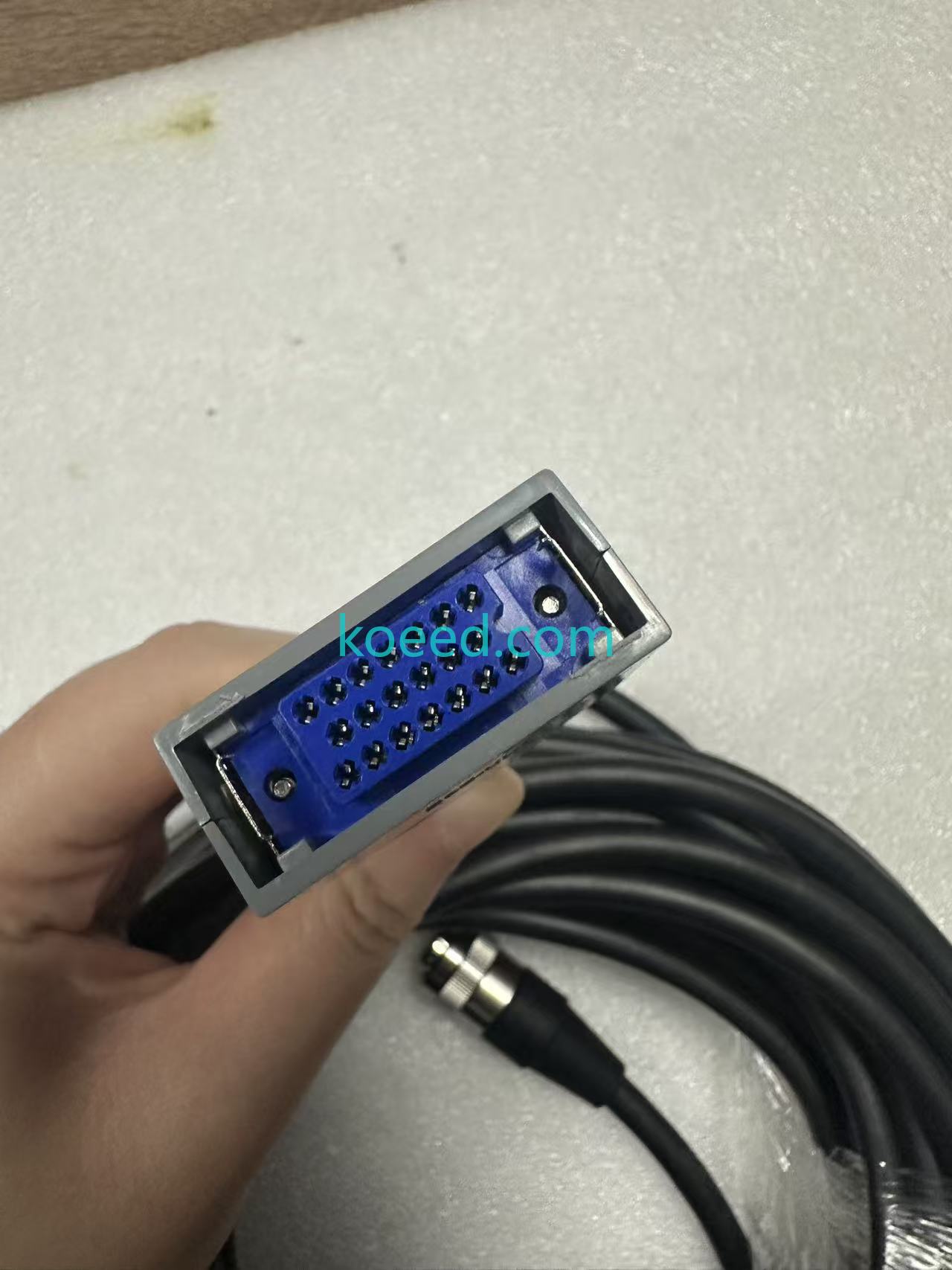
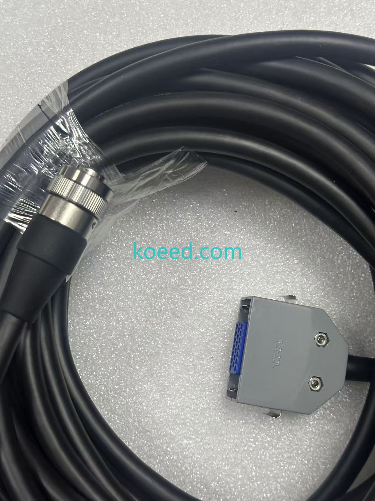
| Connector Type | 20-pin MR-style male to pendant interface | Frequently mismatched pin count | Reuses original shells |
| Shielding | Full braided/foil shield, 360° termination | Foil-only, partial drain | Depends on splice quality |
| Jacket Construction | Oil-resistant, industrial-grade | General-purpose PVC | Original jacket, new splice sleeve |
| Safety Loop | Dual-channel deadman / enable returns intact | Not always dual-channel | High mismatch risk |
| Controller Compatibility | RJ3, RJ3iB pendant interfaces | Model-dependent | Unverified |
| EMI / Noise Immunity | Designed for welding & servo-dense cells | Poor in high-noise environments | Degraded shield continuity |
| Certification / Compliance Path | CE / RIA-aligned cable module | Usually undocumented | Voids original compliance |
| Typical Lead Time (2026) | Expedited global shipping available | Weeks, opaque supply | Zero lead time, high rework rate |
Nomenclature decoded: what the suffix tells you
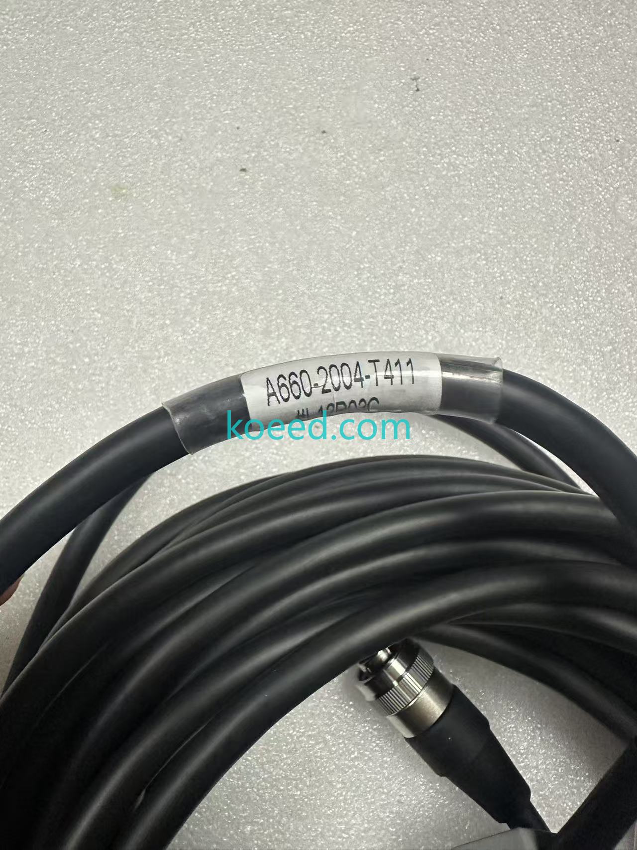
FANUC cable modules use a suffix block after the dash number to encode length and routing hardware — for example #L11R03DB, #L12R03C and #L22R03C appear in the A660-2004-T411 family, along with a 30 m field variant often listed as L=22M. The L value defines overall length and the R value the bend/tie anchor position. Reading these correctly is the difference between a drop-in fit and a cable that binds at the pendant strain relief.
⚠️ Pro-Tip: Verify before you order
Photograph your existing nameplate and measure the installed run before ordering. A 10 m cable on a 12 m pendant hook will fail at the strain relief within months. Match the full dash-suffix, not just A660-2004-T411. Cross-check stock and variant options on the Koeed product page.
3. Visual Gallery: Inspection Reference Set
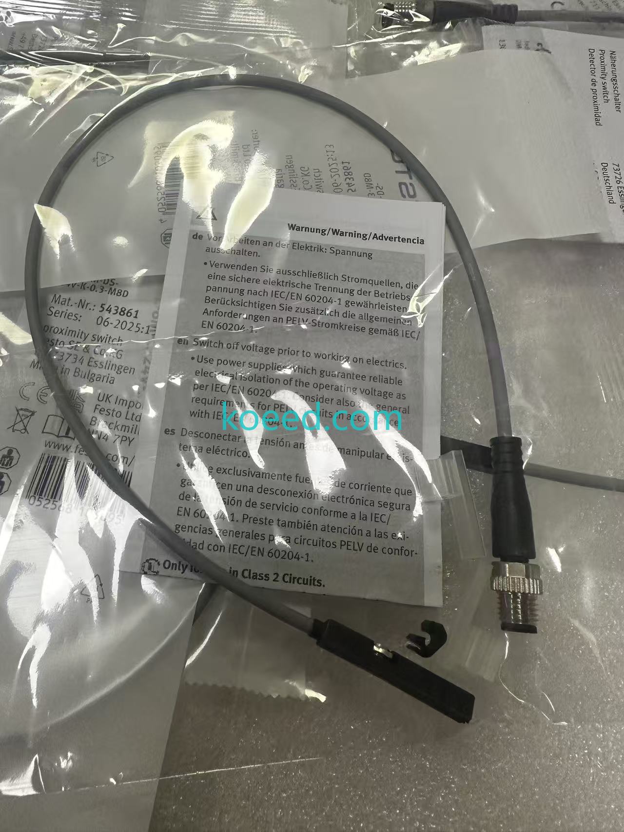
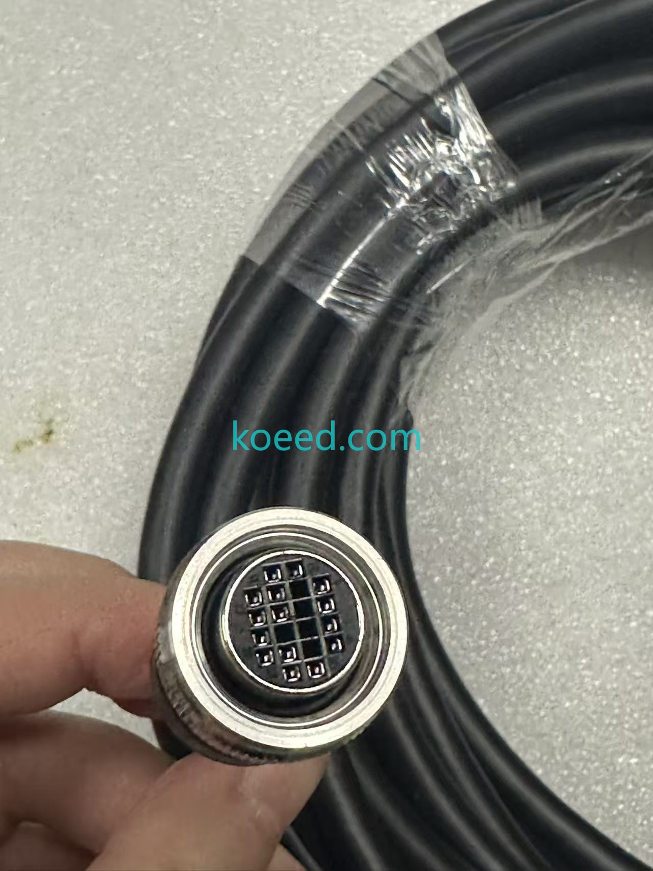
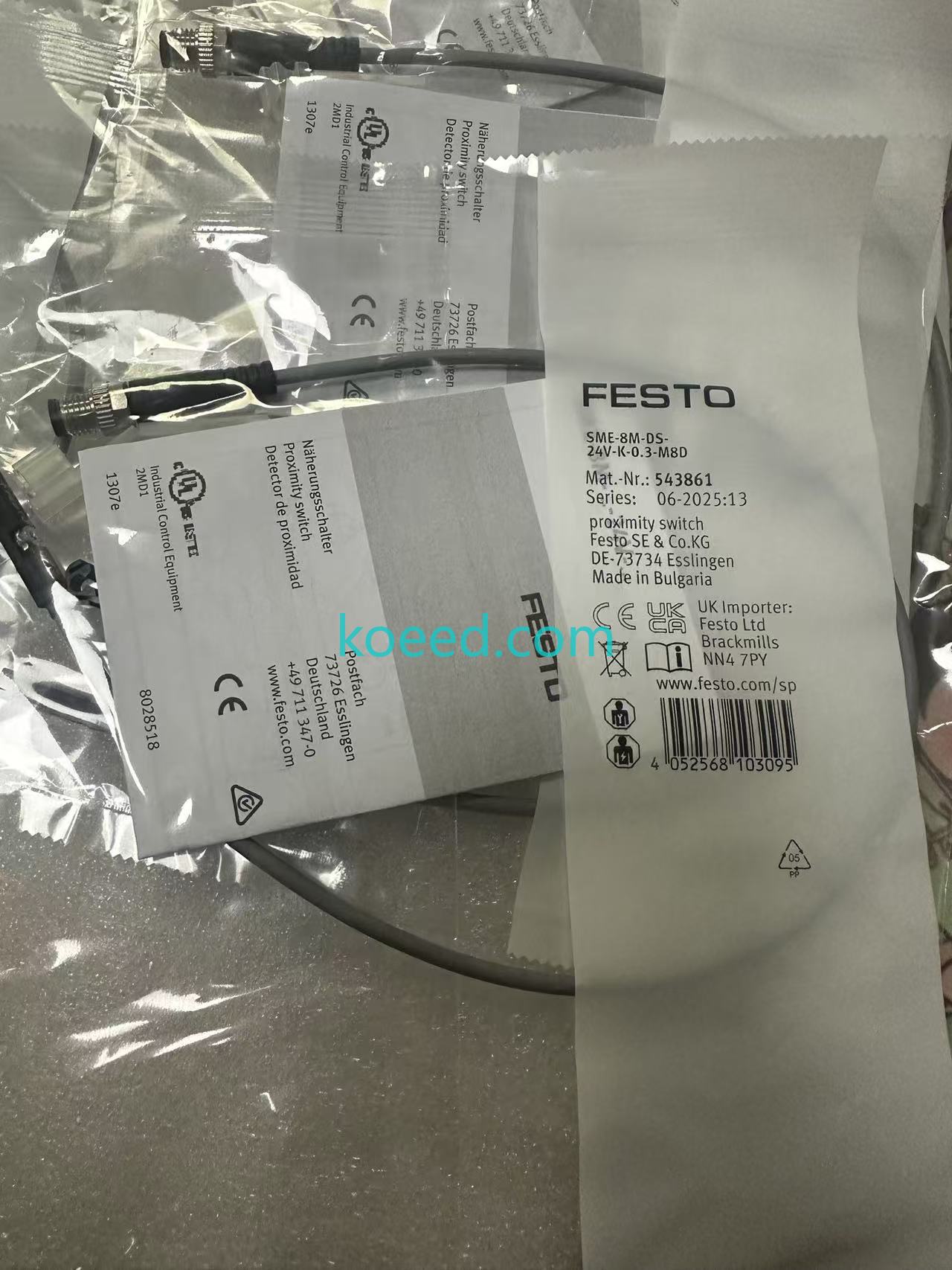
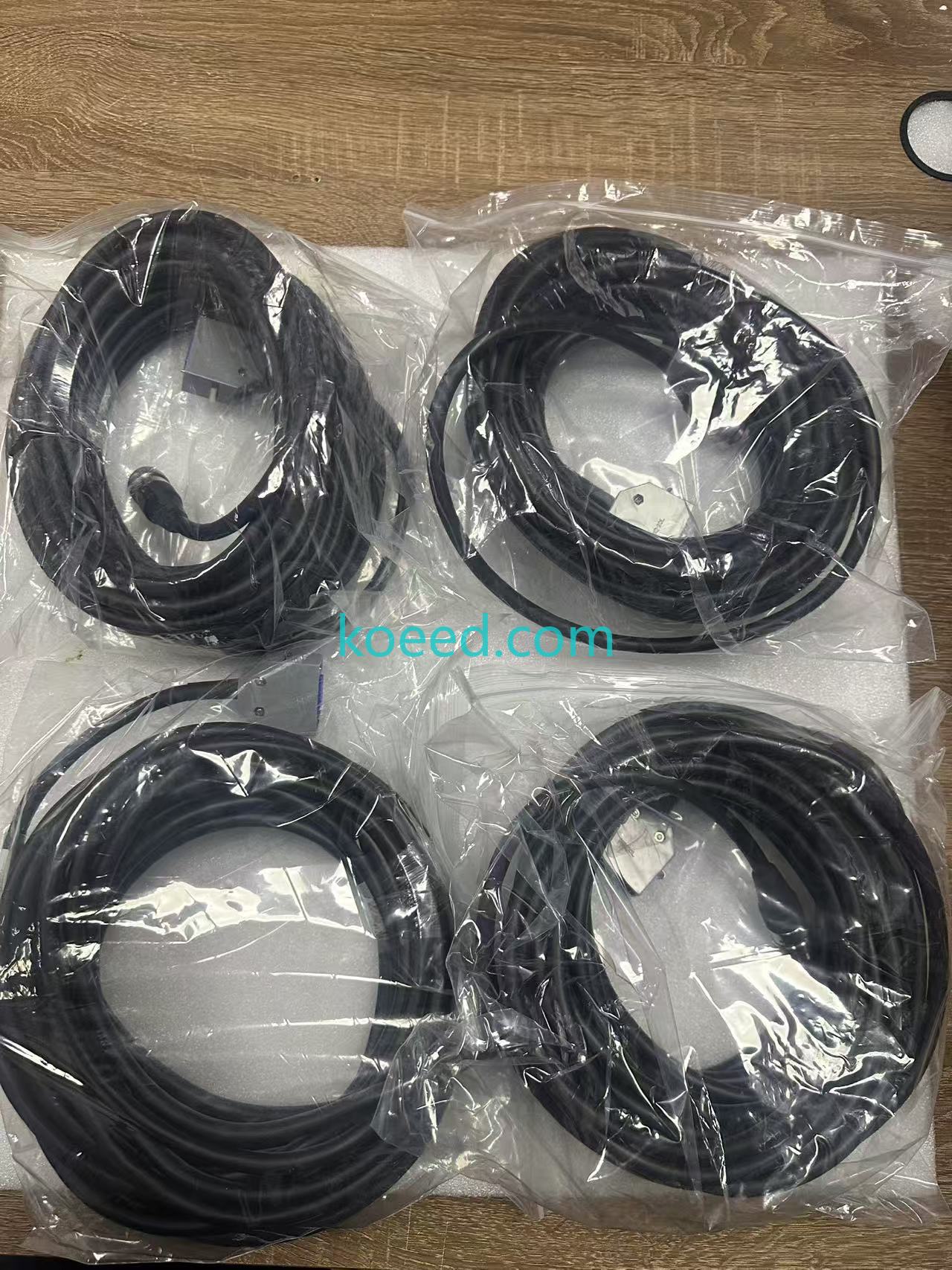
Use the reference gallery below to pre-verify connector orientation, shell keying, strain-relief boot geometry and jacket condition prior to installation. Photograph your removed unit from the same angles to shorten fault-finding considerably.
4. Maintenance & Troubleshooting: Extending Cable Life to 2030+
Pendant cables fail in a predictable sequence. Treat the list below as a diagnostic ladder — work top to bottom and stop when the symptom is eliminated.
Failure ladder & corrective action
- Intermittent pendant blanking when the hook swings. Almost always an internal conductor fracture 100–200 mm behind the strain relief. Confirm by flexing the cable slowly while watching the pendant display. Action: replace the assembly — do not re-terminate a fractured multi-conductor bundle.
- E-stop / deadman faults with no physical damage. Check the enable-switch return path and connector seating first, then verify shield continuity to chassis. A floating shield mimics a safety-circuit fault in noisy cells.
- Communication errors logged as network faults. Before escalating to your IT/OT team, swap the pendant cable. Shield degradation is the classic false positive in diagnostics dashboards.
- Pendant works at rest, faults under servo load. Indicates EMI coupling — inspect for a broken shield drain wire or a cable routed alongside VFD/motor leads. Restore original separation and clipping distance.
- Hard no-comms after a maintenance window. Bent or pushed-back contacts in the 20-pin connector. Inspect with a loupe; replace if any contact cannot be re-seated to full depth.
Pro-tips for long-term reliability
- Respect minimum bend radius — never tighter than the reference in Fig. 10, both at the pendant boot and at the controller gland.
- Support the weight, not the connector. Use the designated tie anchor position encoded in the dash suffix; hanging load on the shell is the number-one killer.
- Log a resistance baseline on each enable channel at install. A 15–20% drift over 18 months is your predictive-maintenance trigger.
- Keep a verified on-site spare. Downtime cost per hour in a tier-one line will exceed the cable cost within a single shift.
- Clean connectors with electronics-grade contact cleaner only — never solvent that attacks the shell polymer or jacket.
💡 2026 Predictive-Maintenance Playbook
Pair each cable replacement with a vibration/flex-cycle log entry in your CMMS. Over two replacement cycles you will be able to forecast failure windows with enough accuracy to schedule swaps inside planned shutdowns — converting unplanned downtime into routine maintenance minutes.
5. Frequently Asked Questions
Which controllers and pendants is the A660-2004-T411 compatible with?
It is designed for FANUC RJ3 and RJ3iB teach pendant systems, terminating in a 20-pin MR-style connector at the pendant interface. Always confirm your controller designation and pendant part number before ordering, as sub-variants within the A660-2004-T411 family differ in length and routing hardware.
What does the standard length of the A660-2004-T411 cable cover?
The standard unit is 10 m (approximately 32 ft). Longer field variants exist within the same part family — you may see listings such as 30 m (L=22M) — so measure your installed cable run, including the service loop, before purchase.
Can I repair or splice a damaged pendant cable instead of replacing it?
Technically possible, practically inadvisable. A splice compromises shield continuity and dual-channel safety-loop integrity, and it invalidates the original CE/RIA compliance path. For safety-critical enable circuitry, a verified replacement assembly is the correct engineering decision.
How does a pendant cable affect IT/OT and OEE data quality?
Every controller-to-MES data point originates at the pendant interface on legacy cells. A degraded shield or marginal contact generates phantom comms faults that inflate MTTR and distort OEE reporting. Restoring cable integrity typically clears these false alarms immediately.
Is expedited shipping available for urgent line-down situations?
Yes — expedited shipping options are listed directly on the product page. For line-down emergencies, contact the team via WhatsApp with your machine model, nameplate photo and required variant so the correct assembly can be confirmed before dispatch.
How should I handle and store a spare pendant cable?
Store coiled at no less than the minimum bend radius, in a dry, UV-shielded location, with connector caps fitted. Avoid tight coiling on a hook, which induces permanent conductor set and reduces flex life.
6. Secure Your Replacement — Request a Quote Today
FANUC A660-2004-T411 — 10M Teach Pendant Cable
OEM-spec construction • 20-pin MR-style interface • RJ3 / RJ3iB compatible • expedited global shipping. Get volume pricing, variant confirmation and technical support from the Koeed automation team.
Product page: 1PC FANUC A660-2004-T411 Teach Pendant Cable — A6602004T411
Request a Quote →Chat on WhatsAppDisclaimer: A660-2004-T411 is a FANUC part designation referenced here for identification and compatibility purposes only. All trademarks and part numbers remain the property of their respective owners. Always verify variant, length and controller compatibility before installation.


