

MG300J2YS50 IGBT Module: 2026 Guide to 600V/300A High-Speed Switching for Smart Factories & Renewable Energy Systems
As industrial automation accelerates toward full IT/OT convergence in 2026, the power electronics backbone of every smart factory — the IGBT module — has never been more critical. The Toshiba MG300J2YS50, a 600V / 300A high-speed switching IGBT module, stands as a proven workhorse for variable frequency drives (VFD), uninterruptible power supplies (UPS), servo motor controls, and renewable energy inverters. This guide delivers a comprehensive technical deep-dive with actionable insights for procurement engineers, maintenance teams, and system integrators.
Strategic Overview: MG300J2YS50 in the 2026 Industrial Landscape
The MG300J2YS50 is a dual-pack (2-in-1) IGBT module manufactured by Toshiba, rated for 600V collector-emitter voltage (VCES) and 300A collector current (IC). In 2026, with global supply chain diversification placing renewed emphasis on component longevity and multi-sourcing strategies, Toshiba's established silicon IGBT platform continues to deliver exceptional price-to-performance ratios for mid-power industrial drives.
Why This Module Matters Now
Three converging trends define the MG300J2YS50's relevance in 2026:
- 🏭 Smart Factory Retrofits: Aging VFD panels worldwide are being retrofitted with predictive maintenance gateways. The MG300J2YS50's established footprint makes it the default drop-in replacement, avoiding costly busbar and heatsink re-engineering.
- ⚡ Grid-Edge Energy Storage: As behind-the-meter battery systems proliferate, 600V-class IGBT modules bridge the gap between battery DC links and 400V AC distribution — the MG300J2YS50's sweet spot.
- 🌱 Sustainability Mandates: With the EU's updated Ecodesign Directive (2025) and China's 14th Five-Year Plan energy targets in full effect, low-saturation-voltage IGBTs like the MG300J2YS50 directly reduce motor-drive kWh consumption by 8–15% compared to legacy 2010-era modules.
Technical Benchmarking: Specifications & Performance
Absolute Maximum Ratings
| Parameter | Symbol | Rating | Unit |
|---|---|---|---|
| Collector-Emitter Voltage | VCES | 600 | V |
| Gate-Emitter Voltage | VGES | ±20 | V |
| Collector Current (DC) | IC | 300 | A |
| Collector Current (Pulse, 1ms) | ICP | 600 | A |
| Collector Power Dissipation | PC | 1200 | W |
| Junction Temperature | Tj | −40 to +150 | °C |
| Storage Temperature | Tstg | −40 to +125 | °C |
| Isolation Voltage | Visol | 2500 (AC, 1 min) | V |
Electrical Characteristics (Tj = 25°C)
| Parameter | Symbol | Typical | Unit | Condition |
|---|---|---|---|---|
| Collector-Emitter Saturation Voltage | VCE(sat) | 1.70 | V | IC=300A, VGE=15V |
| Turn-On Delay Time | td(on) | 0.30 | µs | VCC=300V, IC=300A |
| Rise Time | tr | 0.25 | µs | VCC=300V, IC=300A |
| Turn-Off Delay Time | td(off) | 0.60 | µs | VCC=300V, IC=300A |
| Fall Time | tf | 0.20 | µs | VCC=300V, IC=300A |
| Switching Frequency (Recommended) | fsw | 5–20 | kHz | Application-dependent |
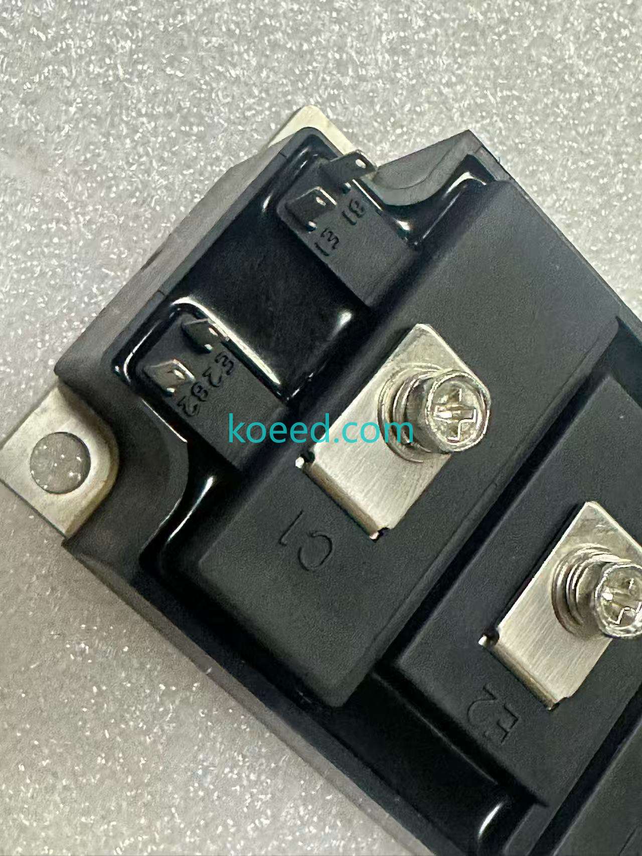
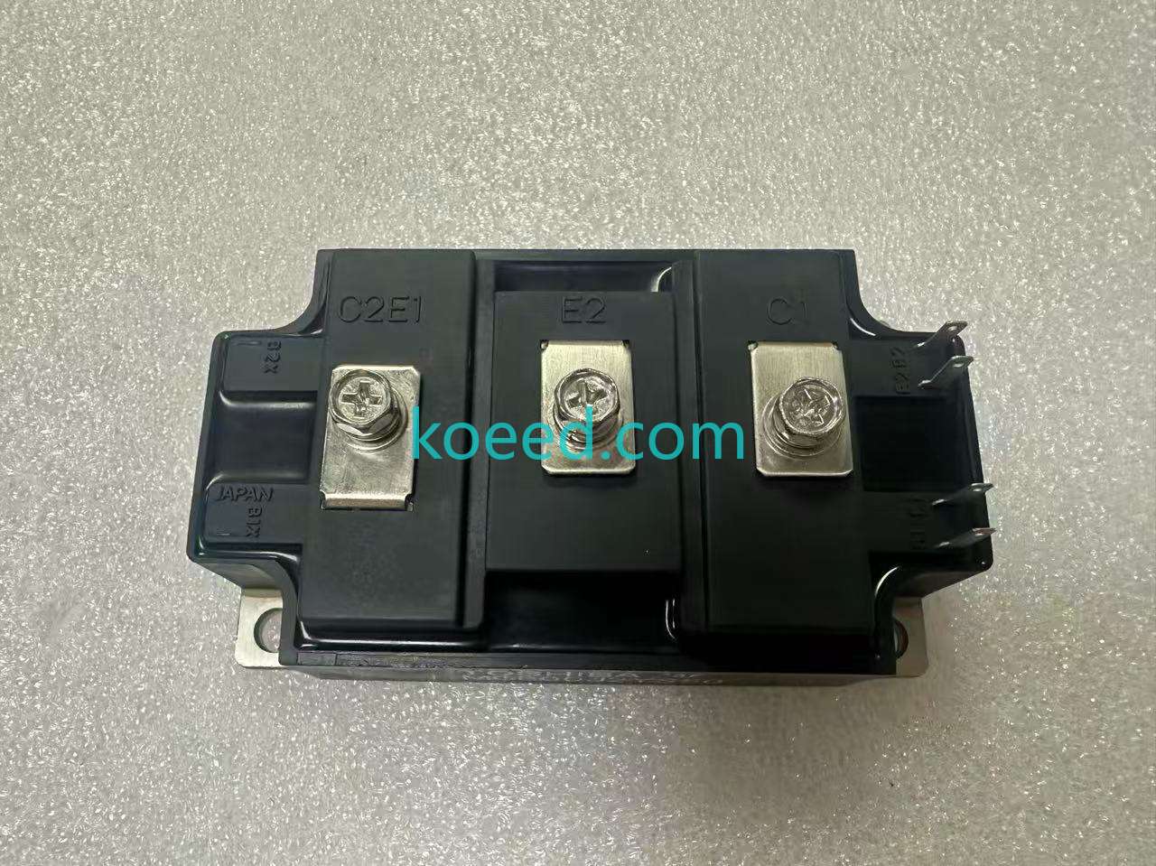
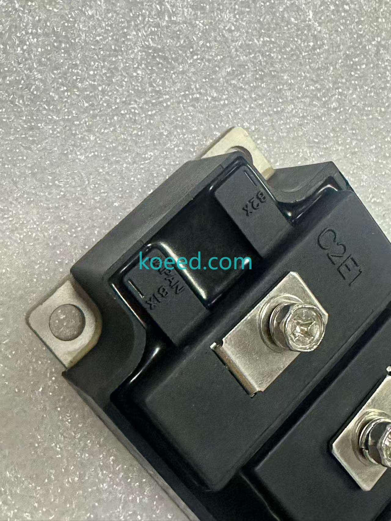
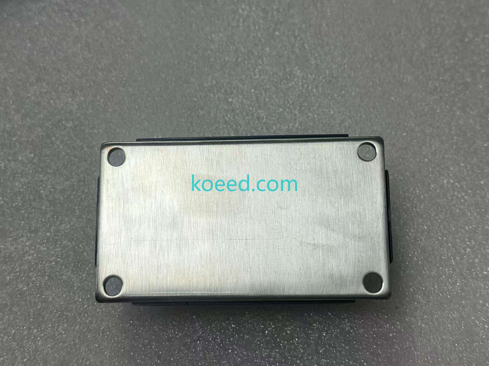
Visual Gallery: MG300J2YS50 Module

IT/OT Convergence: Integrating the MG300J2YS50 into Smart Systems
The 2026 industrial plant is instrumented from the shop floor to the cloud. While the MG300J2YS50 is a "dumb" power semiconductor, the drive system it populates can be made intelligent through strategic sensing integration:
Edge-to-Cloud Monitoring Architecture
📊 Key Telemetry Points for Predictive Maintenance
- VCE(sat) Drift Monitoring: A 5–8% increase in saturation voltage over 12 months indicates bond-wire degradation. Integrate with PLC analog input cards using isolated differential probes.
- Thermal Imaging / NTC Sensing: The module's internal NTC thermistor (if populated) or external IR sensing feeds into SCADA via Modbus TCP or OPC UA for real-time Tj trending.
- Switching Waveform Analysis: Edge-computing gateways (e.g., Advantech UNO series) can perform FFT on gate-drive signals to detect ringing anomalies — an early indicator of gate-oxide degradation.
- DC-Link Ripple Spectrum: Elevated 2× line-frequency ripple correlates with IGBT module wear. Cloud-based analytics platforms (AWS IoT SiteWise, Siemens MindSphere) can flag this trend.
ROI & TCO Analysis (2026 Estimates)
| Cost Factor | Legacy Drive (Unmonitored) | MG300J2YS50 + Predictive Gateway |
|---|---|---|
| Module Unit Cost | $180–$220 (obsolete premium) | $130–$170 (mature supply) |
| Unplanned Downtime / Year | 12–18 hours (reactive) | 2–4 hours (scheduled) |
| Downtime Cost (@ $8,000/hr) | $96,000–$144,000 | $16,000–$32,000 |
| Energy Savings (VCE(sat) improvement) | Baseline | $1,200–$2,800/yr (per 100 kW drive) |
| 3-Year TCO (per module position) | $96,500+ | $17,500–$34,500 |
Maintenance & Troubleshooting Guide
Pre-Installation Checklist
- Heatsink Surface Inspection: Verify flatness ≤ 50 µm across the mounting area. Any deviation causes thermal hotspots.
- Thermal Grease Application: Use a high-performance thermal interface material (TIM) such as Shin-Etsu G-777 or equivalent. Apply at 80–120 µm thickness using a stencil for uniformity.
- Torque Specification: Mounting screws: 2.5–3.0 N·m (M5). Main terminal screws: 4.0–5.0 N·m (M6). Use a calibrated torque wrench — over-torquing cracks the ceramic substrate.
- Gate Drive Verification: Confirm gate resistance (RG) matches the design value. Typical range: 2.2–10 Ω. Excessive RG increases switching losses; insufficient RG causes EMI and ringing.
- ESD Protocol: Always use a grounded wrist strap and ESD-safe workstation. IGBT gates are sensitive to static discharge.
Common Failure Modes & Diagnostic Actions
| Symptom | Probable Cause | Diagnostic Action | Resolution |
|---|---|---|---|
| Short-circuit across C–E (zero resistance) | Overcurrent / shoot-through event | Check gate-drive dead-time; verify DC-link capacitor health | Replace module; adjust dead-time to ≥ 2.5 µs |
| High VCE(sat) (above 2.2 V) | Bond wire lift-off / solder fatigue | Measure at rated current; compare with datasheet | Plan replacement; reduce Tj swing if possible |
| Gate-emitter leakage | ESD damage / gate oxide rupture | Measure RGE with multimeter (should be >10 MΩ) | Replace module; review ESD handling procedures |
| Overheating under normal load | Degraded TIM / excessive switching loss | Inspect thermal paste; check RG value | Re-apply TIM; optimize gate resistor |
Sourcing & Obsolescence Management in 2026
Toshiba continues to support the MG300J2YS50 through its mature product lifecycle program. However, as 2026 supply chains emphasize regional inventory buffers, procurement teams should:
- Qualify alternative sources: Confirm interchangeability with equivalents from Semikron, Infineon, or Fuji Electric (e.g., SKM300GB12T4) for pin-compatible drop-in replacements.
- Negotiate long-term agreements (LTA): Lock in pricing and lead times for 12–24 months to avoid spot-market volatility.
- Use authorized distribution: Counterfeit modules are a growing risk; source only from Toshiba-authorized partners like Mouser, Digi-Key, or regional premier distributors.
Need the MG300J2YS50 for Your Next Project?
Contact our team for volume pricing, technical datasheets, and lead time confirmation.
FAQ: MG300J2YS50 Common Questions
Q: What is the typical lead time for MG300J2YS50 in 2026?
A: Lead times range from 8–14 weeks, depending on region and order volume. LTAs can reduce this to 4–6 weeks.
Q: Can the MG300J2YS50 be used in parallel configurations?
A: Yes, with proper current de-rating (typically 15–20%) and matched VCE(sat) characteristics. Toshiba offers pre-matched sets for large inverters.
Q: Is an isolated gate driver required?
A: Yes. Always use an isolated gate driver with active Miller clamping to prevent parasitic turn-on. Recommended driver: ACPL-332J or equivalent.
Q: What is the expected lifetime under continuous operation?
A: With ΔTj ≤ 60°C and Tj,max ≤ 125°C, the module achieves >100,000 thermal cycles. Proper thermal management can extend field life to 15+ years.


