

DMF50161N-FU-FW Optrex FSTN Graphic LCD: 2026 Industrial HMI Retrofit & IT/OT Integration Guide
1. Strategic Overview: The DMF50161N-FU-FW in the 2026 Industrial Landscape
As industrial enterprises accelerate their Industry 4.0+ transformations through 2026, a critical tension has emerged: the need to modernize legacy equipment without triggering costly full-scale rip-and-replace projects. The Optrex DMF50161N-FU-FW — now manufactured under the Kyocera Display brand — sits precisely at this inflection point. This 240×128 dot-matrix FSTN (Film Super-Twisted Nematic) monochrome graphic LCD module delivers the rugged reliability that industrial environments demand while providing a clear migration path toward IT/OT convergence.
In 2026, the global industrial display market has shifted decisively toward solutions that bridge legacy parallel-interface architectures with modern edge-computing gateways. The DMF50161N-FU-FW, powered by the battle-tested Toshiba T6963C graphics controller, remains one of the most widely deployed HMI display engines across CNC machinery, PLC operator panels, medical diagnostic equipment, and process control instrumentation. Its continued availability through authorized channels like Koeed ensures that maintenance teams can sustain long-lifecycle equipment well past its original OEM end-of-support dates.
🏭 Key Value Propositions for 2026
IT/OT Bridge: The T6963C's well-documented parallel protocol allows seamless integration with modern IIoT gateways (e.g., Advantech UNO series, Siemens IOT2050) via low-cost MCU-based protocol translators, enabling real-time display data capture for cloud analytics without modifying the original PLC logic.
Sustainability Compliance: Extending the service life of existing industrial equipment by 8–12 years through display replacement directly supports corporate ESG targets by reducing e-waste and avoiding the carbon footprint of manufacturing new machinery.
Predictive Maintenance Enablement: When paired with a current-sensing backlight driver, degradation of the LED backlight can be trended over time — a simple yet powerful input for condition-based maintenance scheduling.
2. Technical Specifications & Benchmarking
The DMF50161N-FU-FW distinguishes itself from generic COG (Chip-on-Glass) alternatives through its robust COB (Chip-on-Board) construction and industrial-grade temperature tolerance. Below is a detailed specification breakdown alongside a comparative benchmark against its closest legacy and modern equivalents.
2.1 Full Technical Specifications
| Parameter | Specification | Notes |
|---|---|---|
| Manufacturer / Brand | Optrex (Kyocera Display) | Japanese precision display engineering |
| Model Variant | DMF50161N-FU-FW | FU = specific variant; FW = LED backlight (White) |
| Display Technology | FSTN (Film Super-Twisted Nematic) | High contrast, wide viewing cone, monochrome |
| Resolution | 240 × 128 dots | Graphic type — pixel-addressable |
| Dot Pitch | 0.50 mm × 0.50 mm | Uniform square pixel geometry |
| Active Area | 120.0 mm × 64.0 mm | W × H |
| Module Outline Dimensions | ~180.0 mm × 100.0 mm × 14.0 mm | Typical; verify against datasheet for exact variant |
| Built-in Controller | Toshiba T6963C (or equivalent) | Industry-standard graphics LCD controller |
| Interface Type | 8-bit Parallel (8080-series compatible) | Direct MCU/MPU bus attachment |
| Backlight | White LED (edge-lit) | FW suffix; longer life than CCFL predecessors |
| Backlight Lifetime | ≥ 50,000 hours (to half-brightness) | At 25°C, rated drive current |
| Supply Voltage (Logic) | +5.0 V DC ± 5% | Standard TTL-compatible level |
| LCD Drive Voltage (VLCD) | Typically −10 V to −14 V (adjustable) | Contrast adjustment via external potentiometer |
| Operating Temperature | −20°C to +70°C | Industrial extended range |
| Storage Temperature | −30°C to +80°C | Survives unpowered warehouse extremes |
| Viewing Direction | 6 o'clock (bottom-view optimized) | Typical for operator-panel applications |
| Contrast Ratio | ≥ 8:1 (typical) | At optimal viewing angle & VLCD |
| Response Time | Rise: ~150 ms / Fall: ~200 ms | Sufficient for HMI; not for video |
| RoHS Compliance | Yes | Lead-free assembly |
2.2 Competitive Benchmarking: Legacy vs. Modern Alternatives (2026 Perspective)
| Criterion | DMF50161N-FU-FW (Optrex/Kyocera) | Generic COG 240×128 LCD | Modern TFT (3.5"–5") Replacement |
|---|---|---|---|
| Construction | COB — robust, field-proven | COG — cost-optimized, fragile FPC | COG + FPC — moderate robustness |
| Controller Protocol | T6963C — universal industry support | ST75256 / UC1608 — fragmented ecosystem | SPI/RGB — requires driver rewrite |
| Firmware Migration Effort | ✅ Drop-in replacement — zero code changes | ⚠️ Driver rewrite required | ❌ Full HMI stack rebuild |
| Sunlight Readability | Excellent (transflective FSTN) | Moderate — varies by supplier | Poor unless high-brightness variant |
| Power Consumption | ~350 mW (logic + LED backlight) | ~200 mW | ~600–1200 mW (backlight dominant) |
| MTBF (Module) | > 100,000 hours | ~50,000 hours | ~60,000–80,000 hours |
| Supply Chain Stability | ✅ Kyocera-backed, multi-year availability | ⚠️ Spot-market dependent | Moderate — 3–5 year lifecycle |
| 2026 Unit Cost (Indicative) | $68–$95 (volume-dependent) | $18–$35 | $45–$120+ |
| TCO Over 10 Years | ⭐ Lowest — no engineering NRE | Medium — re-qualification risk | Highest — redesign + validation costs |
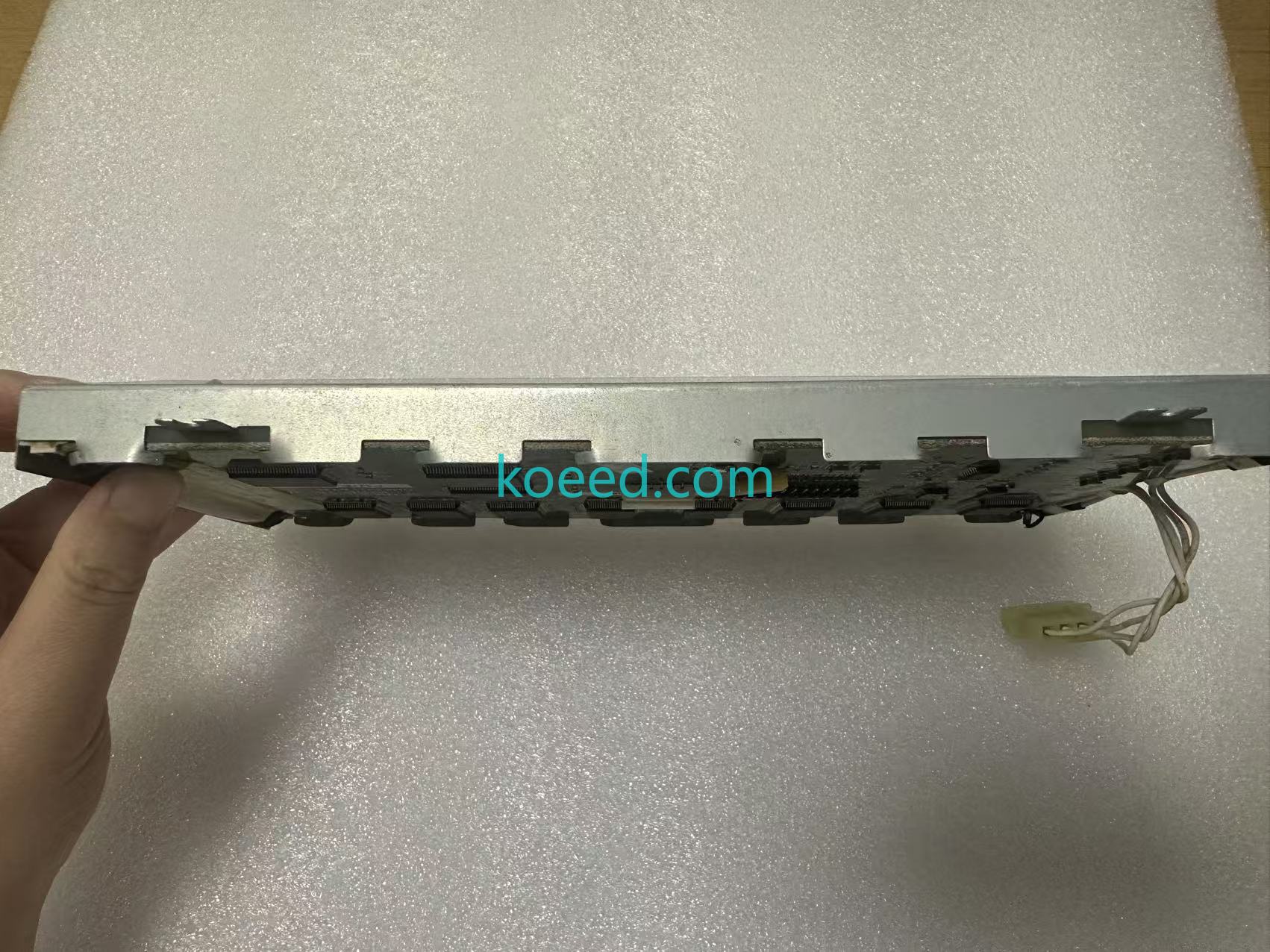
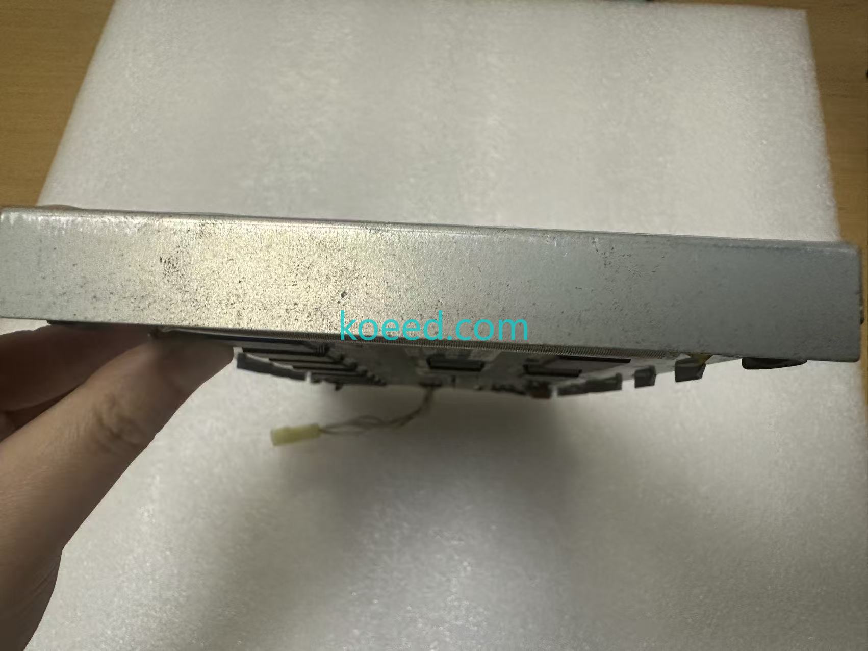
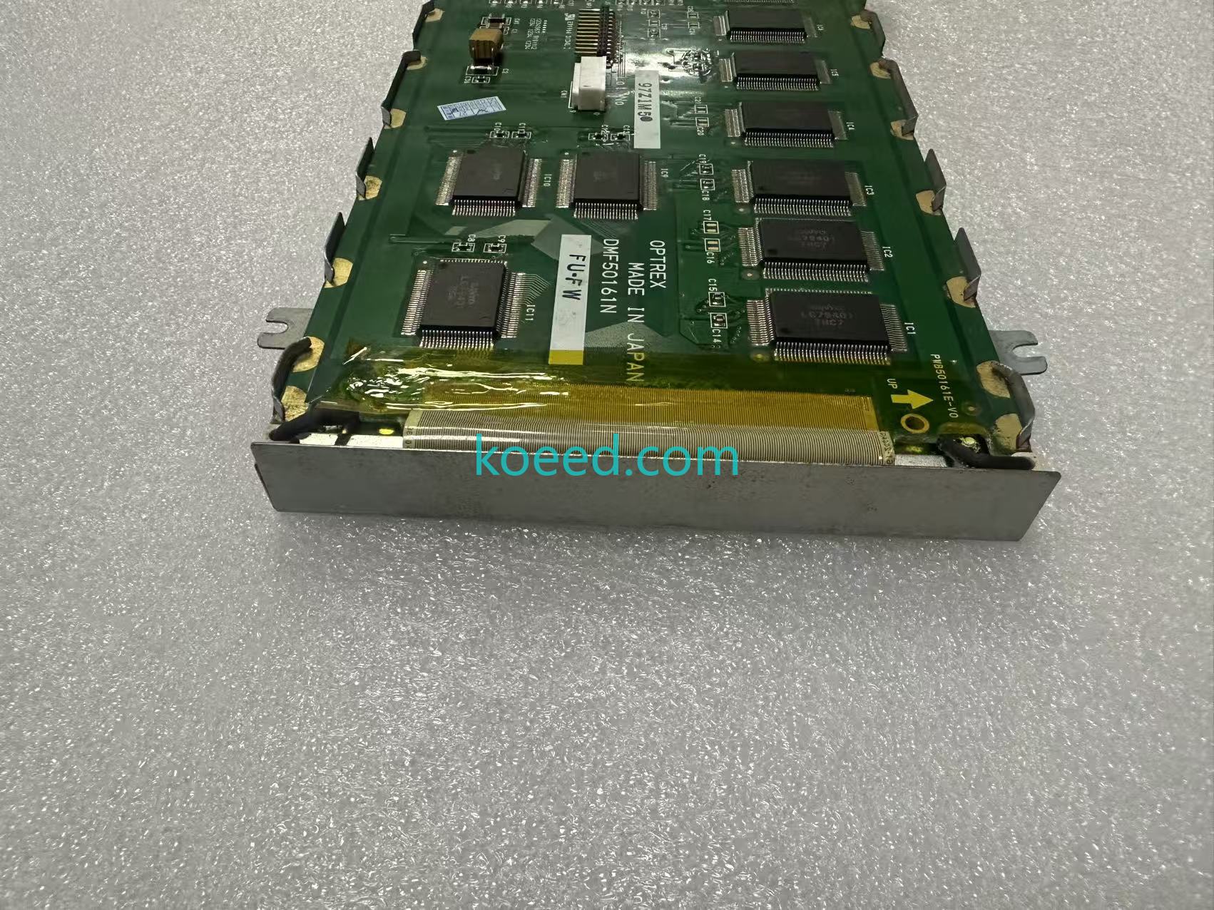
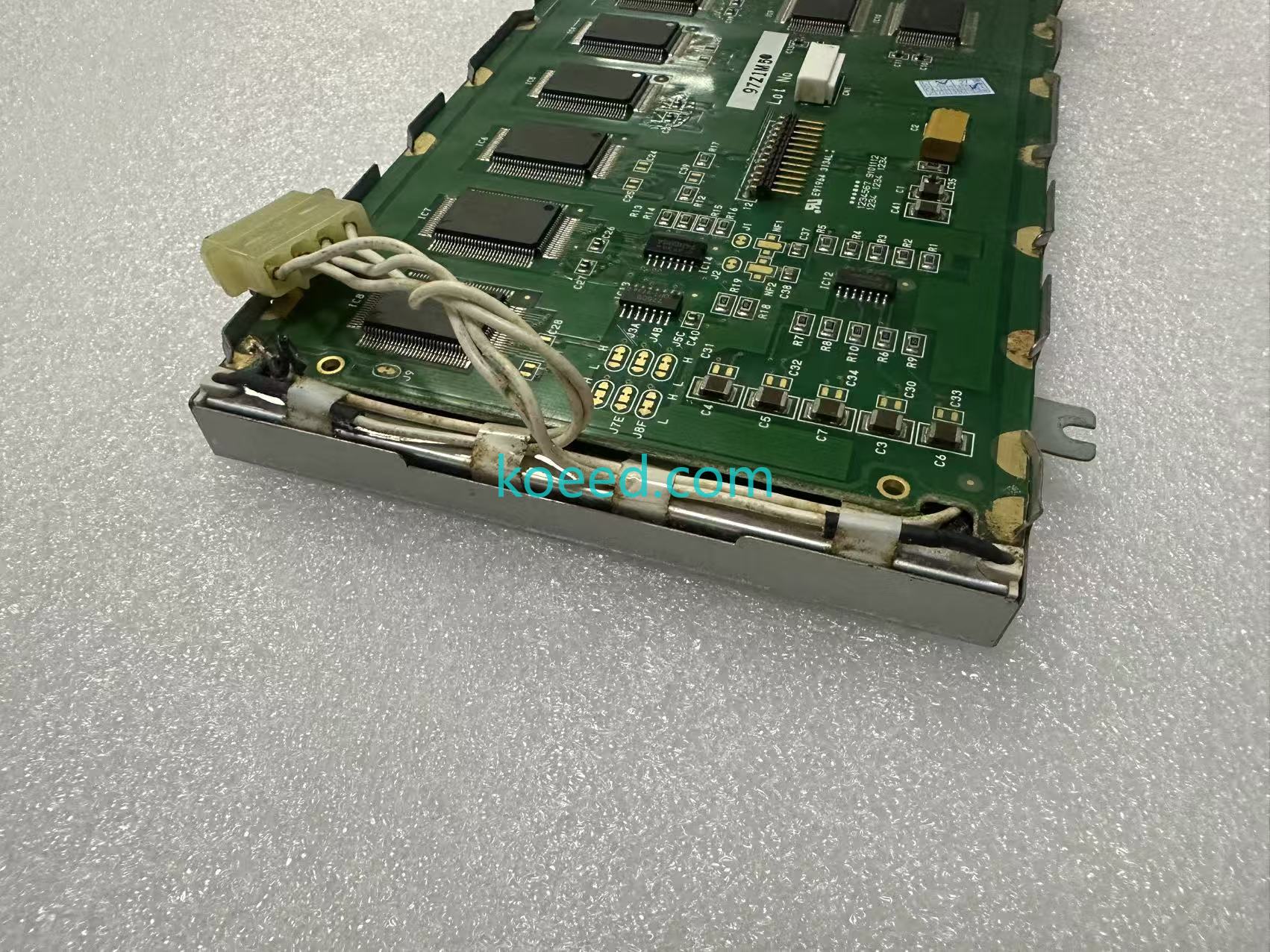
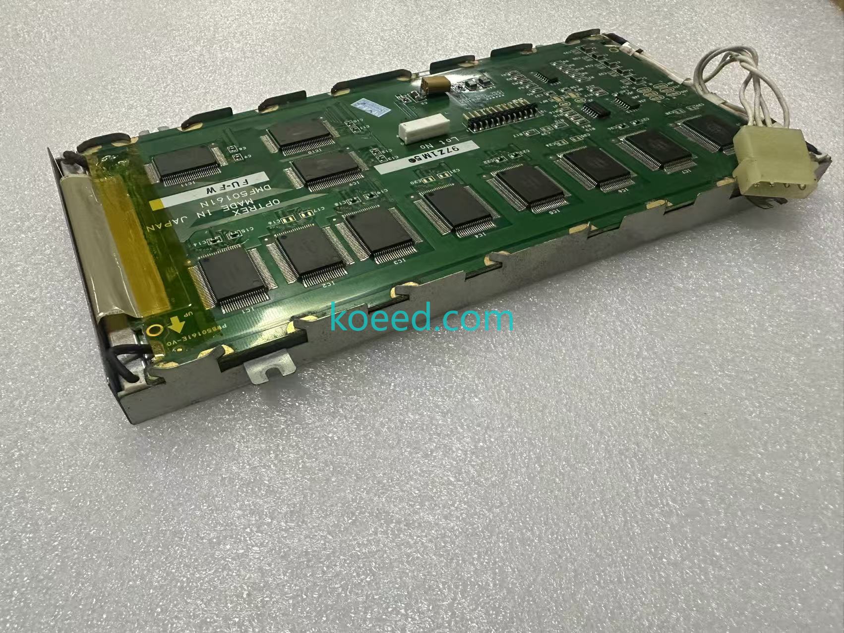
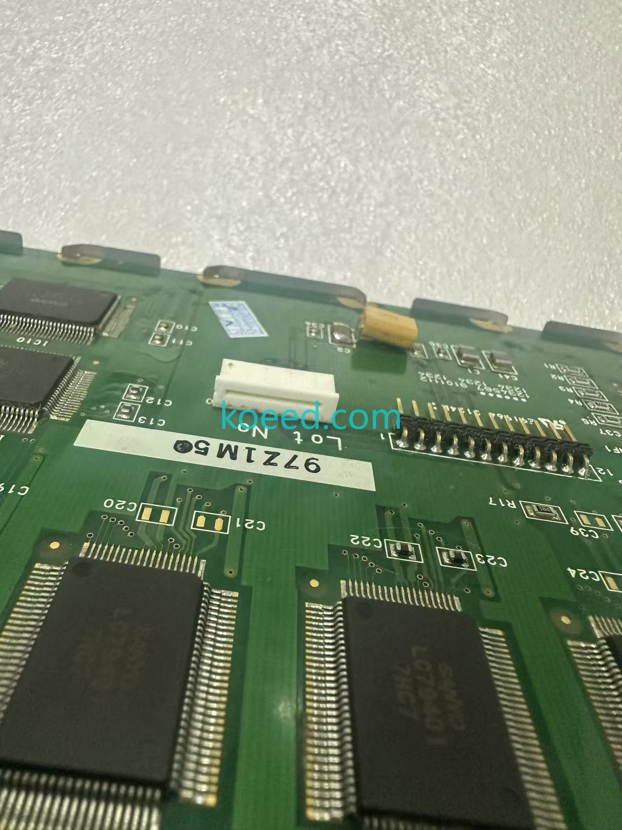
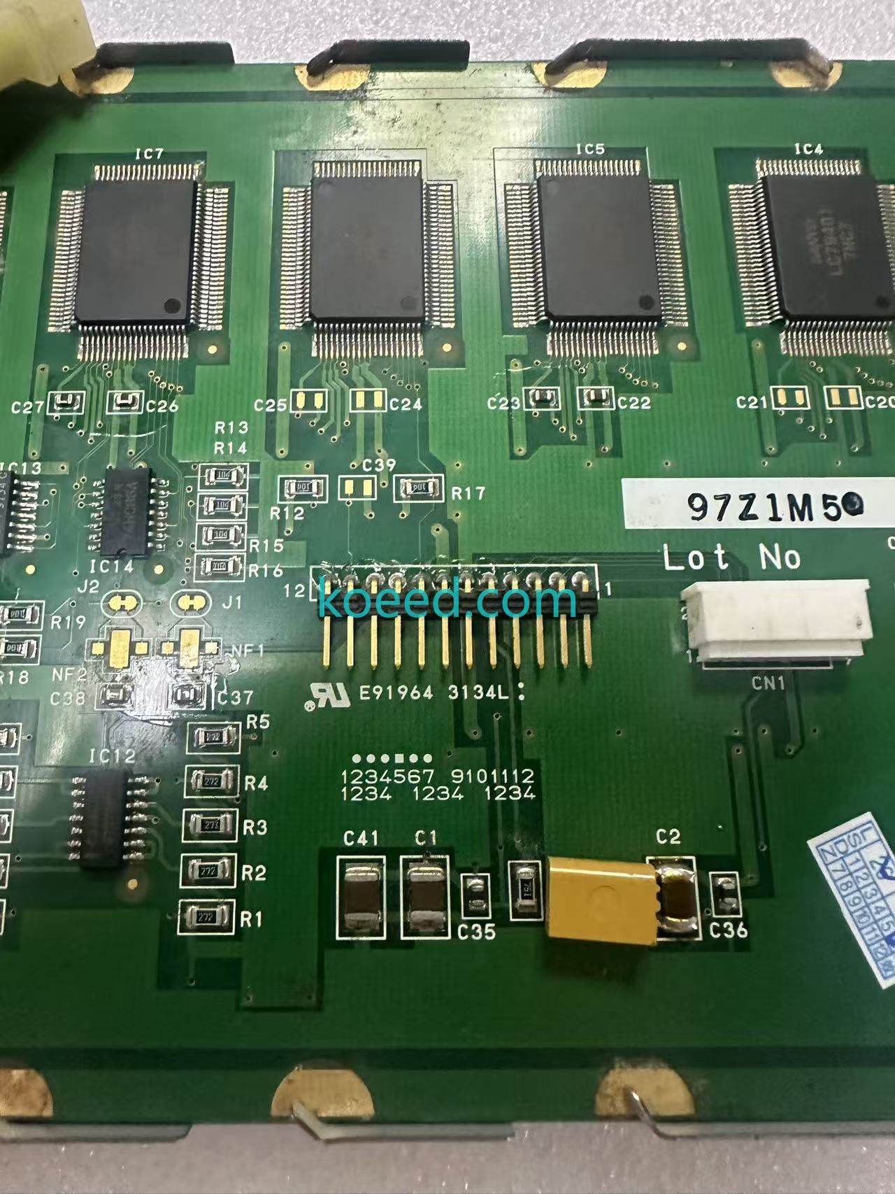
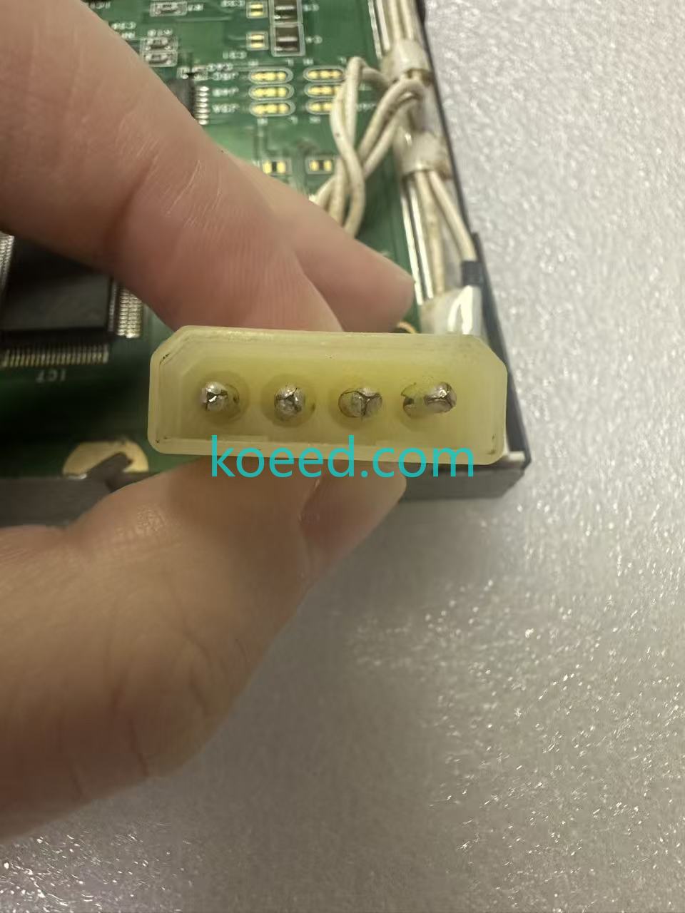
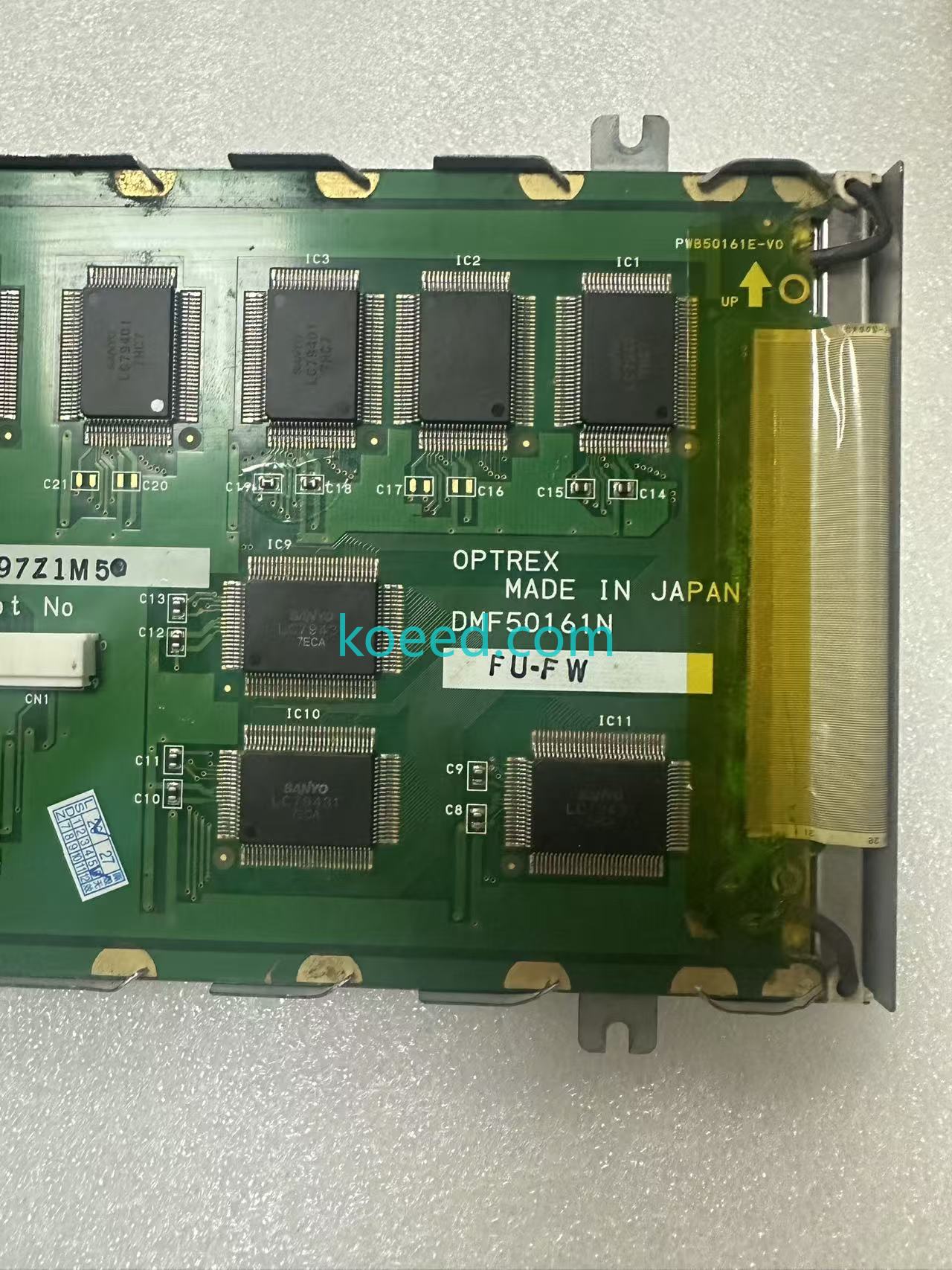
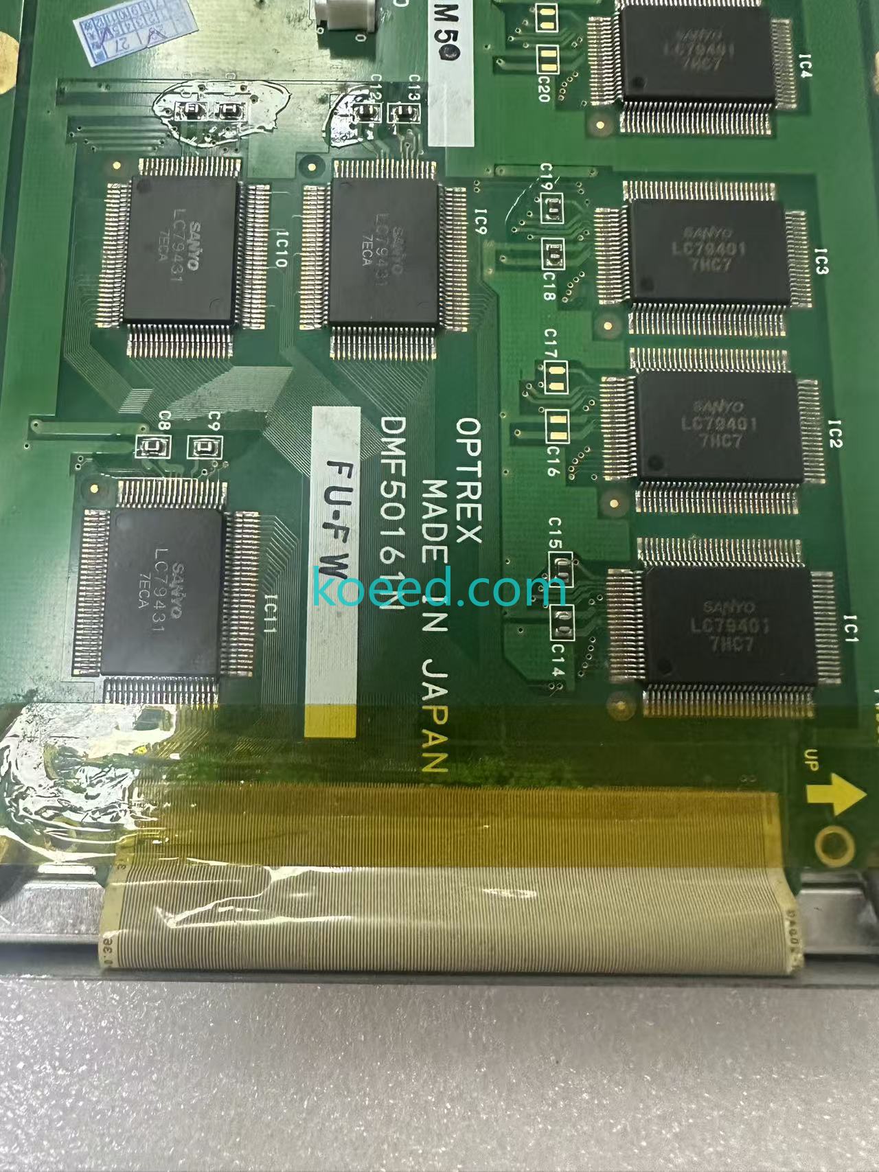
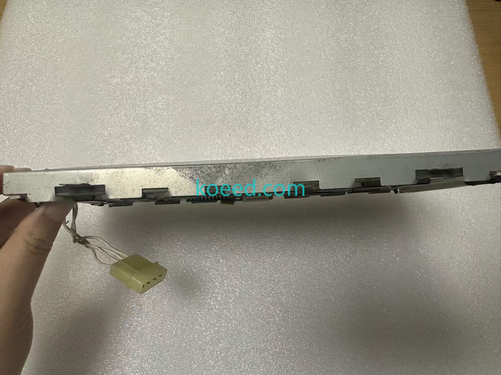
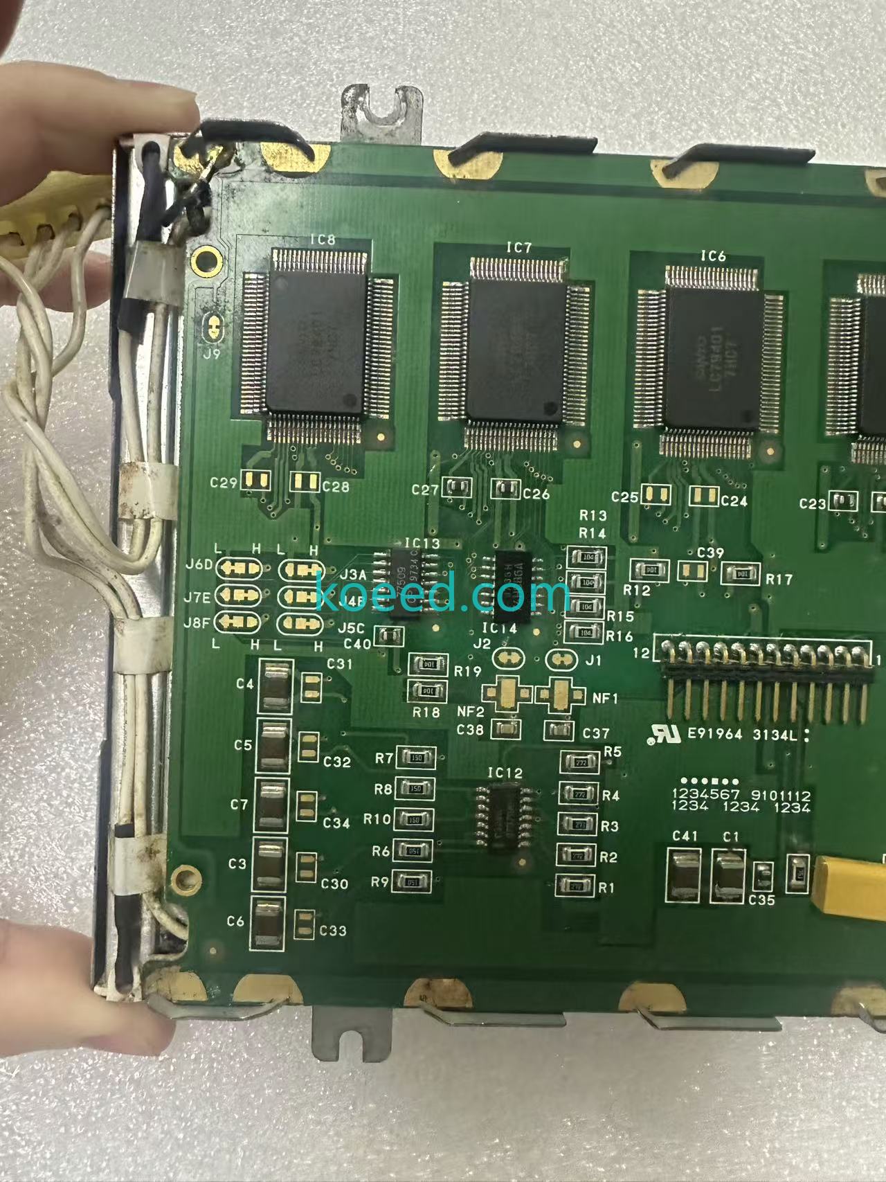
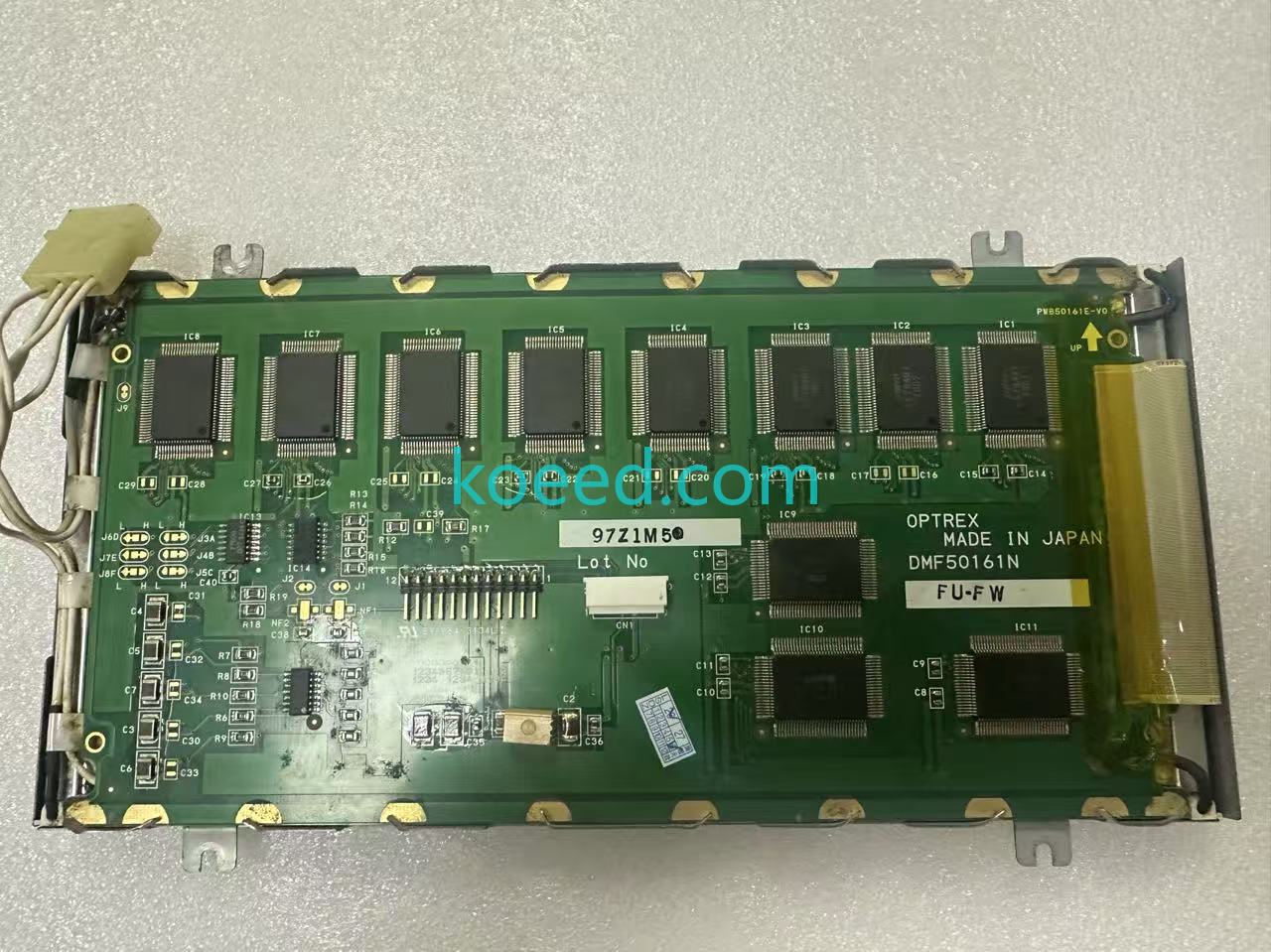
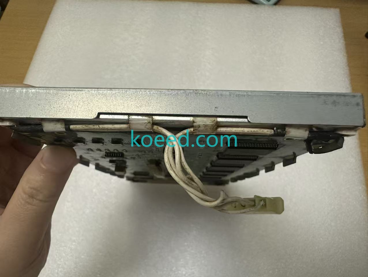
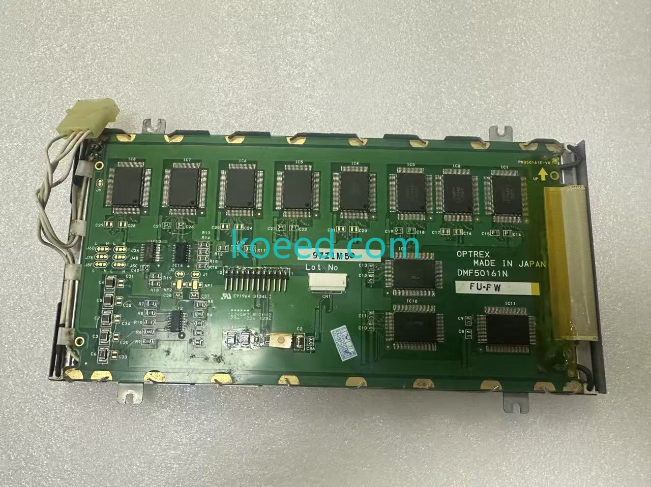
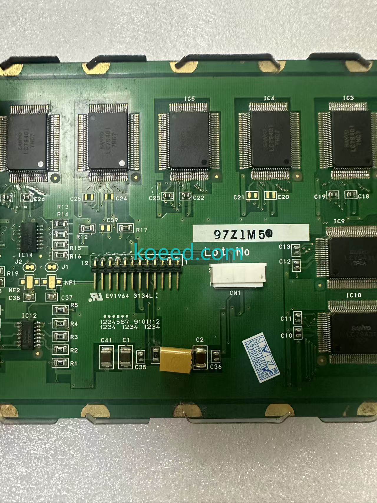
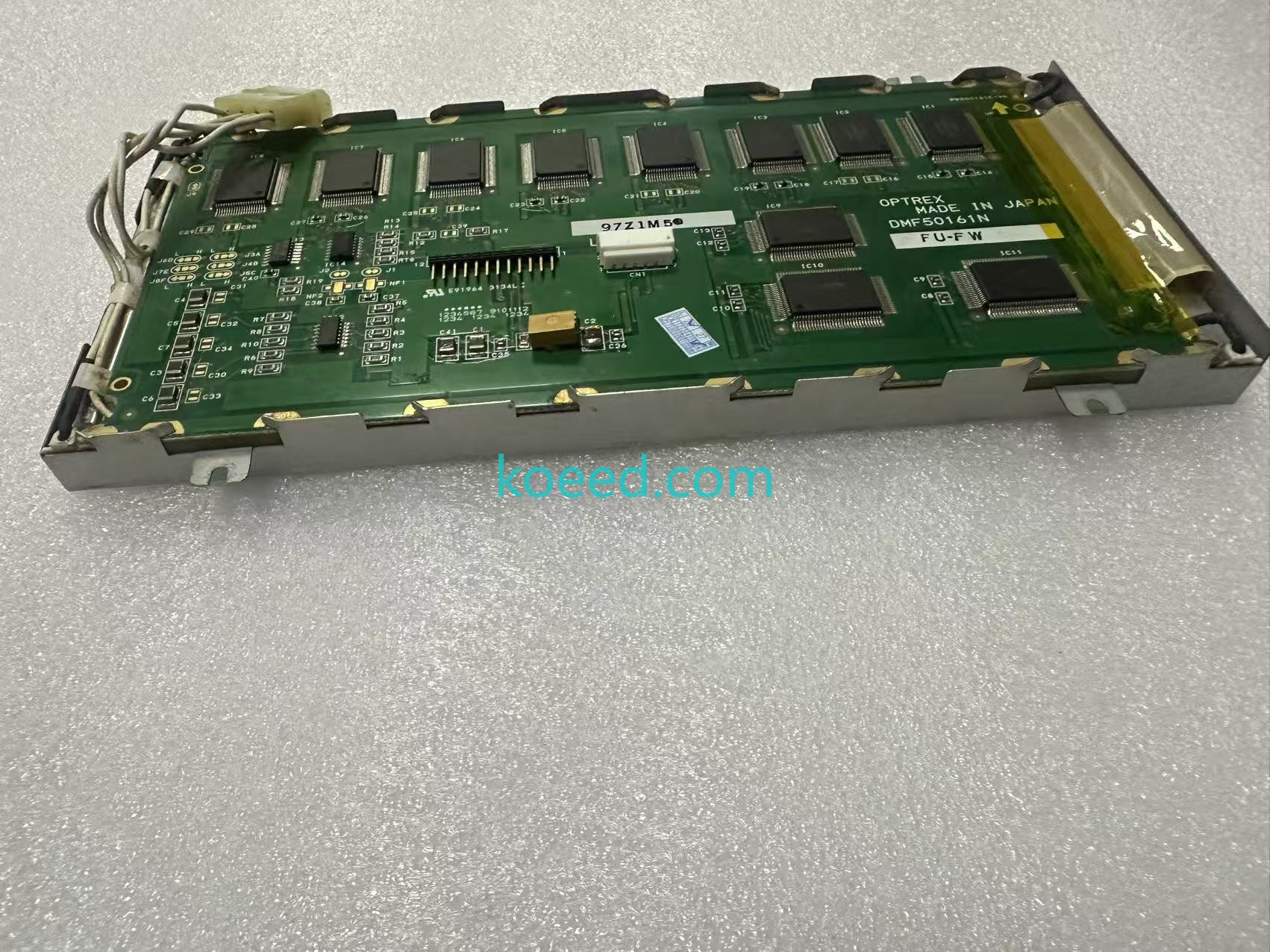
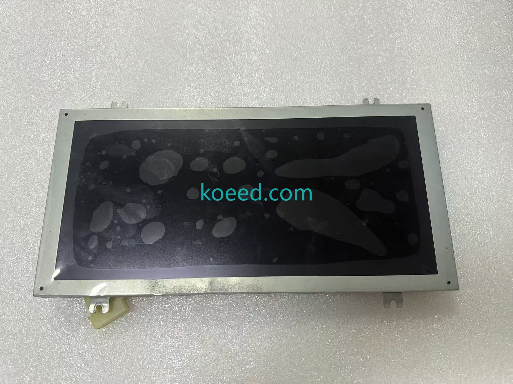
3. Visual Product Gallery — DMF50161N-FU-FW
Below is a comprehensive visual reference of the DMF50161N-FU-FW module. These images capture the module from multiple angles, including PCB details, connector orientation, backlight assembly, and packaging — essential for incoming inspection and integration planning.
4. IT/OT Convergence & Predictive Maintenance Strategy (2026 Framework)
4.1 Bridging the T6963C Parallel Bus to the Cloud
One of the most compelling use cases for the DMF50161N-FU-FW in 2026 is its role as a data exfiltration point in brownfield IIoT deployments. Because the T6963C uses a straightforward 8-bit parallel protocol with well-defined timing, a low-cost microcontroller (e.g., ESP32-S3 or STM32G4 series) can be placed in sniffing mode on the display bus — capturing all screen-write transactions without interfering with the primary HMI function. This non-intrusive approach enables:
📡 Parallel Bus Sniffing Architecture
Step 1 — Physical Tap: A high-impedance buffer (e.g., 74LVC245) mirrors the 8-bit data bus, /WR, /RD, C/D, and /CE lines to the sniffer MCU without loading the original circuit.
Step 2 — Protocol Decode: The sniffer MCU reconstructs T6963C command sequences and extracts numerical values displayed on screen — temperatures, pressures, cycle counts, alarm codes.
Step 3 — Edge Processing: Lightweight analytics (moving average, threshold detection, anomaly scoring) run locally on the sniffer MCU.
Step 4 — Cloud Ingestion: Processed data is forwarded via MQTT-SN over Wi-Fi 6 or NB-IoT to Azure IoT Hub / AWS IoT Core / Ignition SCADA for centralized dash-boarding.
4.2 Predictive Maintenance: Beyond Simple Repair
The DMF50161N-FU-FW's white LED backlight offers a quantifiable degradation curve that can be leveraged for predictive maintenance. By 2026 standards, the following monitoring techniques are considered best practice:
| Monitoring Parameter | Method | Degradation Threshold | Action Trigger |
|---|---|---|---|
| LED Backlight Current Draw | High-side current-sense amplifier (INA219) | +15% drift from baseline | Schedule preventive replacement within 90 days |
| Display Contrast Consistency | VLCD voltage monitoring at contrast pot wiper | >±0.5 V shift from calibrated setpoint | Flag for recalibration; possible LCD degradation |
| Logic Supply Voltage Ripple | ADC sampling on 5V rail (AC-coupled) | >100 mVp-p ripple | Investigate PSU capacitor aging |
| Display Frame Rate Consistency | Timestamp analysis on /WR strobe pulses | Inter-strobe gap >2× baseline median | Host MCU performance degradation alert |
5. Installation, Maintenance & Troubleshooting Guide
5.1 Mechanical Integration and Pinout Verification
Before replacing an existing module, always verify the connector pinout against the original Optrex datasheet (revision D or later). The DMF50161N-FU-FW typically uses a 20‑pin or 22‑pin dual‑inline header (2.54 mm pitch). Key signal groups include data bus D0–D7, control lines (/WR, /RD, C/D, /CE), power (VDD, VSS, VLCD), and backlight anode/cathode. A reversed VLCD connection can permanently damage the LCD panel; double‑check polarity before power‑on.
5.2 Contrast Adjustment and Temperature Compensation
Install a 10 kΩ to 20 kΩ potentiometer between VLCD and VSS (or a dedicated VLCD supply pin, depending on module variant). Set VLCD to approximately −12 V at room temperature as a starting point. If the operating environment experiences temperature swings greater than 20°C, consider replacing the fixed potentiometer with a thermistor‑compensated network (NTC + fixed resistors) to automatically adjust contrast and maintain optimal readability across the industrial temperature range.
5.3 Backlight Driver Considerations for Longevity
The white LED backlight array is rated for 50,000 hours at its nominal current (typically 120–180 mA at ~3.3 V forward voltage). To extend lifetime and reduce thermal stress, derate the drive current by 15–20% below the maximum specified. Use a constant‑current LED driver (e.g., CAT4101 or PAM2804) with soft‑start capability to avoid inrush transients. Monitor the driver’s thermal pad temperature — sustained junction temperatures above 70°C will significantly accelerate lumen depreciation.
5.4 Standard Troubleshooting Sequence
| Symptom | Likely Cause | Corrective Action |
|---|---|---|
| No display, backlight off | Missing VDD or backlight supply | Check 5V logic rail and LED driver input; verify cable continuity |
| Backlight on, blank screen | VLCD too low / absent, or no display data | Adjust VLCD to –12 V; scope /CE and /WR lines for activity |
| Dim or uneven backlight | Aging LEDs or current imbalance | Measure forward current; replace backlight strip if below 70% rated flux |
| Faded or ghost images | Contrast drift, VLCD instability | Re‑calibrate VLCD; check potentiometer for open wiper |
| Intermittent pixel defects | Loose FFC/connector or dry solder joint | Reseat all connectors; reflow suspect joints on module PCB |
6. Sourcing, Authenticity & Lifecycle Management
In 2026, the DMF50161N-FU-FW remains in active Kyocera production for industrial MRO, but procurement must be approached with care. The following guidelines will help you secure genuine, full‑specification modules:
🔍 Authentication Checklist
1. Label Inspection: Genuine Kyocera/Optrex labels include a laser‑etched serial number and a QR code that decodes to a Kyocera‑controlled URL. Counterfeits often use printed stickers with random numbers.
2. PCB Silkscreen: Authentic boards have “OPTREX” or “Kyocera” silkscreen with a 4‑digit revision code. Missing or smeared silkscreen is a red flag.
3. VLCD Voltage Check: Power up the module with a known‑good T6963C initialization sequence and adjust VLCD to achieve a nominal 8:1 contrast ratio. Counterfeit clones frequently require VLCD voltages outside the −10 V to −14 V range, or show poor contrast uniformity.
4. Backlight Color Temperature: Measure the LED backlight’s color temperature (should be 6000 K – 7500 K). Clones often use lower‑quality LEDs with a yellowish or bluish tint outside this range.
Need a Reliable Source for Genuine DMF50161N-FU-FW Modules?
Koeed stocks factory‑fresh Kyocera DMF50161N-FU-FW modules with full traceability and a 12‑month warranty. Our team can also assist with custom adapter boards, bus sniffer integration, and volume pricing for fleet‑wide retrofit projects.


